
Configure Modelling Extents
Note: This topic relates to Dynamic Modelling.
Dynamic modelling can generate various outputs including contact surfaces, volumes, block models and more. It can be useful to constrain the output of data so that data is only generated within a specified boundary constraint.
You can constrain the output of dynamically-modelled data to one or more of the following:
-
A topography.
-
A prototype model hull. One is created automatically to constrain the output combined solid if no extents are specified. See Block Model Properties.
Tip: Try out different prototypes and see the impact they have on modelled outputs. To do this, just change the prototype model and rerun your workflow. Simple!
-
Perimeter strings projected to form a boundary.
-
A loaded wireframe volume or volumes.
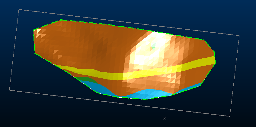
A combined volume constrained by a boundary string (dashed green)
Any combination of constraint types is possible; for example, you may want to clip all data above a topography but generate a combined solid within a prototype hull cuboid, or to simply clip all data outside a delimiting perimeter, providing it also falls inside a small, partly-intersecting pit phase shell volume.
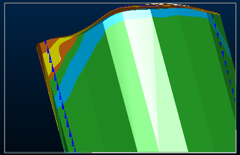
A volume constrained by a boundary string (Plane inclination = 15 degrees) and a prototype model
Tip: Rename a loaded extents object using the Dynamic Modelling Properties screen.
Create Modelling Extents
To define one or more extent constraints for dynamic modelling:
-
Load desurveyed drillholes. Typically, you would do this using Drillhole Importer.
-
Load all data you intend to use to constrain modelled outputs (topography, prototype model and so son).
-
Display the Dynamic Modelling Framework framework.
-
Add your loaded drillholes.
-
In the Extents section and complete the following as required:
-
Expand the Select proto list and choose a loaded topography surface.
Note: If a prototype model extent is already associated with your workflow (there can be only one prototype in a workflow), the label Proto selected appears instead. In this situation, you need to locate the prototype model in the list below and click "X" to delete it first.
-
Expand the Add topo list to pick a topography to constrain data to below the surface only. You can add one or more surface topographies to a workflow.
-
Expand the Add boundary list to either pick a loaded closed string perimeter, or to digitize a new boundary. One or more boundary strings can be used to constrain data.
Note: By default, boundary string data is projected vertically to constrain data, but you can change the Plane azimuth and Plane inclination used for projection using the Dynamic Modelling Properties control bar once an extent is selected in the list below (you will need to re-run the workflow to see the effect).
-
Expand the Add volume list to select one or more closed wireframe volumes. Data will only be created within wireframe data.
Note: If no extents are specified, a prototype model is created automatically and assigned to the workflow.
Note: Where multiple extent types are specified, or multiple instances of the same extent, data is constrained to the overlap of all items (like the centre of a Venn diagram, but in 3D).
-
-
Save your project
Create Rotated Model Prototype Extents
It can be necessary to use a rotated prototype model that is oriented more appropriately to the structures being modelled. This could be the case say, where cross-cutting structures align to a particular trend that would be more accurately (block) modelled using a rotated prototype.
To create a rotated model prototype for boundary constraint (and block modelling):
-
Define prototype model extents in the Extents section of the Dynamic Modelling framework. See Create Modelling Extents, above.
-
Display the Dynamic Modelling Properties control bar. See Dynamic Modelling Properties.
-
Select the prototype extents item.
The Dynamic Modelling Properties control bar updates to show information about the selected extents.
-
In the Dynamic Modelling Properties control bar, expand the Proto section.
-
Change the Rotation Mode to Fixed.
The Rotation Angle fields below become active.
-
Up to three rotations are possible, using the rotation angle convention Z-X-Z. Enter degrees value(s) for Rotation Angle 1 (and optionally 2 and 3).
-
In the Dynamic Modelling framework, click the green play button
 to recreate the prototype model with the new rotation(s).
 -
Review the rotated prototype hull and adjust as required, recreating the prototype each time.
-
Re-run the Dynamic Modelling workflow to recreate outputs using the new prototype extents.
-
Save your project.
Delete Extents
To delete a boundary constraint from your dynamic modelling workflow:
-
Load the project containing your Dynamic Modelling configuration.
-
Display the Dynamic Modelling framework.
-
Expand the Extents section if required.
-
Locate the extent to remove in either the Proto model, Topographies, Boundary Strings or Boundary Volumes section and click "X" to delete it.
Note: You can also disabled an extent temporarily, without deleting it. See further below.
Change a Boundary String Projection Direction
To change the direction at which boundary string 'cutting' is performed:
-
Load the project containing your Dynamic Modelling configuration.
-
Display the Dynamic Modelling framework.
-
Expand the Extents section if required.
-
Select the extent to constrain using a boundary string.
-
Display the Dynamic Modelling Properties control bar.
-
Adjust the Plane Azimuth and Plane inclination to define the plane from which boundary data will be projected (orthogonally). For example, to define a North-South plane, set Plane Azimuth to 90 and Plane Inclination to -90.
-
In the Dynamic Modelling framework, click Re-run All.
-
Save your project.
Deactivate Extents Temporarily
To temporarily deactivate a boundary constraint (without deleting it):
-
Load the project containing your Dynamic Modelling configuration.
-
Display the Dynamic Modelling framework.
-
Expand the Extents section if required.
-
Select the extent to temporarily deactivate.
-
Display the Dynamic Modelling Properties control bar.
-
Uncheck Enabled.
-
In the Dynamic Modelling framework, click Re-run All.
Outputs are recreated, ignoring the unchecked extent.
-
Save your project.
Tip: You can also deactivate an extent by unchecking in the Extents list.
Related topics and activities