
Block Models
Block models are typically created as part of the geological modelling process, but can also be created during the grade estimation, mine optimization and mine design processes which form part of the general mine planning cycle.
These block models can be displayed, formatted and filtered in Studio. Some products offer extended functionality relating to block models, such as Studio RM, which provides tools for advanced grade estimation and implicit modelling, whilst Studio Geo offers one-click updating of implicit models from live drilling data and automatic regeneration of a domain-coded model.
An example of a block model displayed in a 3D window - several visualization options are available
These 2D or 3D models are used to represent, in an exploration or mining environment, a material mass (rock, sand, soil) with its associated characteristics defined as numeric or alphanumeric attributes. These attributes include for example:
- Geological attributes:
- Rock types.
- Oxidation codes.
- Rock density.
- Mineralization zone identifiers.
- Mineralization grades.
- Grade estimation parameters or statistics.
- Mine planning (operational) attributes:
- Ore categories.
- Optimization envelope flags.
- Processing categories.
- Bench or level numbers.
- Dates (planned, actual).
These models play an important role as they are used as direct input into the following open pit and underground processes:
- Structural block model creation and updates from live data (Studio Geo)
- Grade estimation and resource and reserve evaluation (Studio RM).
- Optimization (Studio NPVS+ and Mineable Reserves Optimizer).
- Mine design (Studio OP and Studio UG).
- Blast design (Studio OP).
- Short term scheduling (Studio OP, Studio UG and Datamine Task Scheduler).
- Reconciliation and grade control (Studio Survey, Studio Mapper and Ore Controller).
What is a Block Model?
A block model consists of closely packed, six sided orthogonal cells (rectangular cuboids). The following types of cells can be found within a block model:
-
Parent cell - the largest cell size permitted in the block model, as defined by the block model prototype.
-
Sub-cell - a division of the parent cell.
The following diagram shows the relationship between the block model, its cells (parent and sub-cells) and the model prototype parameters:
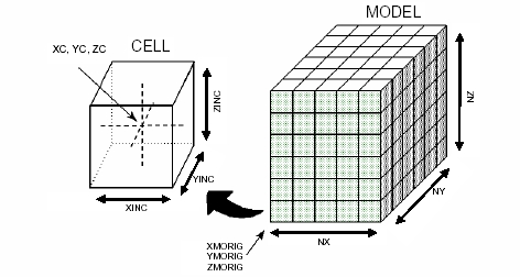
In an unrotated block model, the following coordinate convention applies:
-
X coordinates increase eastwards
-
Y coordinates increase northwards
-
Z coordinates (elevation) increase upwards.
Block Model Terminology
The following terminology is used in association with block models:
-
A block model prototype consists only of the block model definition i.e. the Implicit fields listed above, but does NOT contain any data table records.
-
A block model contains both the basic model definition fields, additional custom fields (examples shown below) and contains data table records.
- Model Origin: the corner of the first parent cell i.e. typically the corner of the cell with the lowest X, Y and Z coordinate (see XMORIG, YMORIG, ZMORIG below)
- Cell: a model block.
- Parent Cell: the largest cell allowed in the model, as defined by the default values for the fields XINC, YINC and ZINC.
- Sub-cell: any cell smaller than the parent cell. Sub-cells lie within the boundaries defined by the parent cell.
- Prototype Model: a model file containing file header information and no records. Used to control other block modeling Processes.
Block Model Standard and Custom Fields
Block Model files and objects contain the following fields:
- XMORIG, YMORIG, ZMORIG *: (X,Y,Z) origin of the model i.e. the corner of the first (cell with lowest X, Y and Z value) ) parent cell and NOT its centroid
- NX, NY, NZ **: number of model parent cells in XYZ directions. The number of cells, in combination with the cell dimensions, defines the extent of the model
- XINC, YINC, ZINC ***: XYZ cell dimensions. If the model is not to contain any sub-cells then these three fields can be Implicit
- XC, YC, ZC **: XYZ coordinates of the cell centre.
- IJK **: numeric Parent Cell identifier, unique for all cells falling within the same parent cell
- MINED: mined-out control field (needs to be added i.e. it is not added by default when a new file is created).
- DENSITY: a standard field (needs to be added) used to store relative density values for the different rock types. If no data is available, the Default Density value is used.
- ZONE: zone control field (needs to be added) for block model optimization and grade estimation (other user defined field names can also be used; multiple zone control fields can be defined)
* These fields are normally Implicit (the values are stored in the File Header and do not appear as columns in the file).
** These fields are normally Explicit i.e. the values are stored as records in the file.
*** These fields are typically stored as Implicit when NO sub-cells are used and as Explicit when sub-cells are used. Fields that contain a constant value throughout the file are usually stored as Explicit fields in order to reduce the size of the file.
Important: Block Models need to be sorted on the field IJK in order to be loaded or used in your application's Processes. Most Processes sort the model before creating the output file. The creation or manipulation of a model file using certain commands (e.g. by using the EXTRA Process) may generate an output file that is not sorted on IJK.
-
Store information in a block model as an Implicit field when the field has a constant value for all records. This will result in the block model file being smaller than if the field was stored as Explicit. The latter would occupy an additional field and records in the data table.
-
Store rock type codes (and other flag fields) as a numeric rather than an alphanumeric field, as this will allow you to perform numeric, statistical and evaluation functions using this data.
Standard and user-defined attribute fields can be assigned to a block model in one of the following ways:
- Transferred from the string or wireframe objects used to generate the block model.
- Using Datamine processes, for example EXTRA or SETVAL.
- Interactively by editing model cells in the 3D window.
- Using the Datamine Table Editor.
Block Models and Grade Estimation
Block models, sample data (point or drillhole data) and geostatistical parameters are typically used as inputs into the grade estimation process.
See Grade Estimation Methods.
Related topics and activities: