|
|
Block Model Properties - General Dialog An explanation of fields and properties |
To access this dialog use:
-
In the Sheets control bar, active 3D window folder, Block Models sub-folder, right-click a blobk model, select Properties,
-
In the Block Model Properties dialog, select the General tab.

|
A Datamine eLearning course is available that covers functions described in this topic. Contact your local Datamine office for more details. |
The Block Model Properties - General dialog is used to define color, display type, exaggeration, display options and sequencing settings.
When a block model is loaded for the first time, the Display Type is set to Quick Section, with the result that the Sequence Column and Sequence Options are grayed out. In order to define and use these options, the Display Type needs to be set to Points, Lines, Blocks or Intersection.
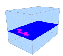
For more information on viewing block models, please see Block Models Introduction; for more information on controlling the position of the block model intersection plane, see the Section Control dialog.
|
|
The settings described here apply to the currently active 3D window and all linked external windows. Independent windows will be unaffected. |
Field Details:
This dialog contains the following fields:
Name: displays the current name of the selected data object overlay. You can edit this name and click OK or Apply to change the model file name within the project. Note that editing the name of a 3D object will not affect the description assigned to the underlying (Source) file - see below. You can edit this if you like, which is the same as using the Sheets control bar menu's Rename option.
Source: shows the name of the loaded object from which the current 3D overlay was derived.
Display Type: select an option here to display your block model as either Points, Lines, Blocks or a Section. Note that the selection made may affect the options available to you in the remainder of the dialog. The following options are available:
-
Points: show the current model as a series of points, with each point representing the volumetric centre of each block cell.
-
Lines: view as a series of lines.
-
Blocks: show shaded model cells.
-
Quick Section: show the model as a section along either the IJ, JK or IK planes (or, by loading the model more than once, several sections simultaneously). Note that this option will display full cells only, and does not rely on a previously defined section plane in memory.
-
Intersection: if selected, you can access one of the previously defined 3D sections in order to display a detailed cross-sectional view of your geological model, including sub-celling. You can also choose to intersect your model with the currently <Active section>, meaning the view will be updated if the active section changes.
For more information on these different formats, see Block Models Introduction.
More information about this visualization option can be found on Datamine's online Knowledge Base:https://datamine.freshdesk.com/en/support/solutions/articles/19000059421-displaying-a-block-model-section-in-the-3d-window -
Unlit: by default, all loaded models that are displayed asBlocks(see above) will be 'lit', meaning a simulated, directional light source is applied. You can opt to show the data without any directional lighting (and thus showing the base color without shading) by selecting this check box.
The image below represents 'lit' block model cells (i.e. theUnlitoption is disabled):
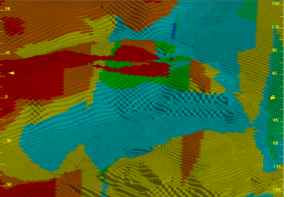
With the Unlit option enabled, the following view is shown: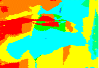
Color: display legends can either be a standard fixed color, or you can choose to color your data according to a display legend:
-
Fixed: select this option to use the same color to render your chosen item. Note that this color will also be used to color data that cannot be matched to a legend interval when the Legend option is chosen (see below).
-
Legend: when this option has been selected, the initial drop-down list in this area can be used to select a predefined legend (system standard or user-created).
-
Column: using the drop-down, select a data column that contains the values to be matched to the selected legend.
As with all legend drop-down lists, once an item has been selected, you can elect to edit the chosen legend or preview it. You can also automatically create a default legend for any selected field:
|
|
Preview the currently selected legend intervals and display properties |
|
|
Edit the currently selected legend using the Legend Manager. |
|
|
Select a default legend for the selected data column if one already exists, or if no default legend is available, the Create New Legend wizard will appear to let you create a new legend. |
RGB: if your data object contains attribute reflecting RGB color information, select them here to color your data using this in-object information. Only numeric fields will be available.
Any color depth is supported; define the Maximum Value for the color attributes. For example:
4-bit color depth is described a Maximum Value of 15 (0-15 = 16 per color channel)
8-bit color depth is described using a Maximum Value of 255 (0-255 = 256 per color channel)
12-bit color depth is described using a Maximum Value of 4095 (0-4095 = 4096 per color channel)
16-bit color depth is described using a Maximum Value of 65535 (0-65535 = 65536 per color channel)
24-bit color depth is described using a Maximum Value of 16,777,215 (0-16,777,215 = 16,777,216 per color channel)
Sequence Column: select a data column from the dropdown for use in sequence animation.
Sequence Options: when a Sequence Column has been defined (see above), the following options are available:
Forwards: sequence the data according the increasing value of the selected attribute.
Single Frame: replace instead of adding to displayed view frames.
Reverse: select this option to play the sequencing animation in reverse, i.e. from the highest record to the lowest record value in the Sequencing Field.
Anim. Rate: this value represents the 'speed' at which the 'steps' are played. The most appropriate value depends on many factors, including the density of the data and how many 'steps' are in a particular animation.
Anim. Step: this value determines the step size in the animation and equates to the number of records displayed/hidden for each frame. It is based on the values in the selected Sequence Column.
Loop: select this checkbox to replay your animation from the beginning once the final 'frame' has been displayed.
Annotate: select a field from the object that will be shown as on-screen annotation during sequence playback. Select the Show Annotation check box to annotate the wireframe with sequence column data. You can control the formatting of the on-screen annotation using the Configure button to display the Sequence Annotation Overlay dialog. Select Configure to define the annotation's font, position and display text parameters, using the Sequence Annotation Overlay dialog.
In the example below, an
annotation attribute has been defined for a block model (IJK) and a wireframe
(ZONE). Each object is supported by its own Sequence Control bar below.
The annotation is displayed for both objects (although configured differently
for each). When the sequence slider of either object is adjusted, the
corresponding annotation will be updated automatically. 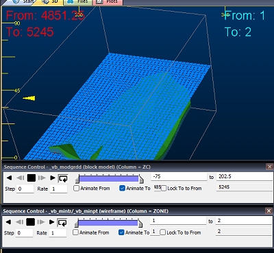
This can be useful for interrogating data with respect to particular attribute
values, or combinations of values. For example, you could render a block
model using two separate overlays (by copying one), then sequence model
1 based on a grade value and model 2 on a density value.
These Sequence Options control how the block model is animated when either a single object animation is played from the Sequence Control dialog or a multiple object animation is started from the Simulation toolbar. |
Exaggeration: this option is only available for Lines and Blocks
display types (see above), and allows the view of each line or block
in the block model data to be magnified. For example, a model viewed
in close up, as blocks, with a cell exaggeration of 50% (meaning that
a gap will exist between cells, the same size as the cell itself)
may look like this:
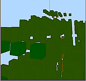
...and the same model viewed with a 25% exaggeration would like this:
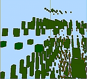
The default exaggeration for model cell blocks is 90%. |
Options: the following additional display options are available:
Show Fill: if selected, the faces of each block, or the interior of each intersection polygon will be filled according to the currently selected colouring options. Available for the Intersection and Blocks display types only.
Show Edges: if chosen, the boundary of the blocks or polygons will be drawn as unlit lines. Available for the Intersection and Blocks display types only.
If both Show Fill and Show Edges options are selected, you can display highlighted edges, e.g.: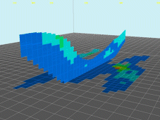
Show Absent: controls whether any cells being coloured by an ‘Absent’ value are drawn. Choosing this option may be useful for getting a better feel for block model extents, while opting out may be better for showing grade boundaries, for example. In the image above, two intersections have been drawn: the horizontal one includes absent cell values (shown in grey), while the vertical intersection only shows those cells with valid values.
As another example, the image below shows an isometric view of a model represented as blocks with absent data included: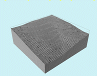
Whereas the following image shows the same model. but with the Absent Data check box cleared: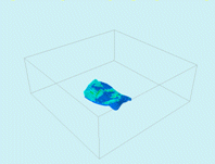
Show Hull: if enabled, the 'bounding box' representing the data extents for the select block model will be displayed as a 3D box on screen.
Show Border: this option is only available if a block model is being viewed as a Quick Section (see above). If enabled, a line will be shown to indicate the extremes of the object model (including absent data).
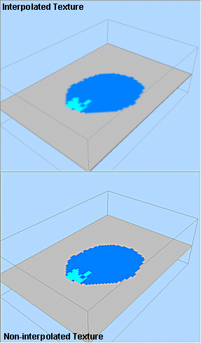
Interpolate: when viewing block model data, you can choose to interpolate the section colors. Interpolated textures show a more 'blended' view of the disparate cell colors and can be useful when a hard boundary between parent cells isn't necessarily desirable. The image below shows (top) an interpolated and (bottom) non-interpolated section display type:
Opacity: using the slider bar, set the transparency level of the selected block model. By default, data is shown at 100% opacity (0% transparency).
Intersection Section: if you have selected to display your model as an Intersection (see above), you can use this drop-down list to pick a section to use to show a slice of your block model.
You
can either choose a predefined section or choose the <Active Section>
option. Selecting this will update the formatting of the wireframe
object so the active section is used to generate an intersection.
Changing the active section updates the view. This can be useful,
for example, where a section definition table has been loaded for
sectional interpretation of drillhole data in the context of an implicitly-modelled
volume.
More about sections, including the active section
concept...

