|
|
Designing in 3D Design and visualization in one place |
Designing in 3D Windows
The 3D window is used for both designing and visualization, and you can swap between optimal environments for both instantly.
"Design commands" are commonly used when modeling geological
data, assisting in designing open pit and underground excavations,
mine planning and scheduling.
Multiple 3D Windows
Your application supports multiple, linked 3D windows.
These additional windows can be additional representations of the current window (and linked to it), either by splitting the screen horizontally and/or vertically, or can be an 'external' floating view that is connected to your primary 3D window data and formatting options. All of these views are linked to a single data source and formatting settings.
Each window is supported by its own Sheets control bar sub-menu.
Independent 3D windows are also available. These allow you to set your own window-specific formatting of overlays, sections, grid and many other scene controls. Independent windows can either be embedded or external/floating.
|
|
You can design your own cursors, even a different cursor for each 3D window (or 3D window split) using the Custom Cursors dialog. |
|
|
Each 3D view will automatically expand its limits to accommodate all loaded data. However, the larger the scene, the more information Studio needs to process. For example, where data is loaded that represents a very large 3D scene (for example, data in different coordinate systems being widely separated over thousands of virtual measurement units), each loaded object represents a much smaller part of the scene than normal. This can give rise to unusual rendering behaviour when 'looking at' a particular part of your data. This could manifest as 'shaking' data where the data falls within such a tiny part of the overall scene, it alternates between coordinates at a precision level. A redraw will resolve this ('rd' quick key). Alternatively, keep your scenes to a manageable size, such as that expected by a single pit operation. |
Datamine's Data Windows: a History of 2D, 2.5D, 3D.....
Previous Datamine products relied heavily on a 2D CAD environment to deliver design commands and functionality.
The Design window was configured to represent 3D data using a 2D slice through the data. This slice of data, always shown face-on to the viewer, was known as the "Design Plane", "Working Plane" or "Design Section".
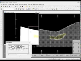
In Studio 2, users were restricted to navigating data by defining this section and updating the screen, then viewing the data in a simple 3D preview window called the Visualizer window. Although linked, a 3D preview would need to be manually updated after design changes to see the effect.
Studio 2 also relied on the presence of a GRAPHICS and SCREEN window to visualize the data files output from processes such as TONGRAD, PPQQPLOT and others.
The
Visualizer
window is no longer available as superior functionality is available
via the 3D windows or supporting functions, such as PDF3D export,
for example.
The parameters governing the position
of the working plane in the
Design window is often referred
to as the "section definition", although this term can be
used to define any flat plane in 3D space.

The last update to Studio 2 was released in January 2011
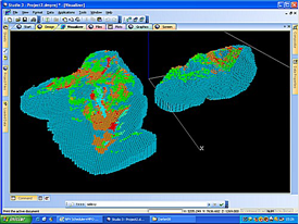
In Studio 3, this framework was extended, primarily by the introduction of an OpenGL-powered visualization window that was derived from another product of the time - Datamine InTouch. The VR window was linked closely with the Design window, allowing users to both engineer and visualize their data by swapping between different views of the same data. Studio 3 also incorporated functionality from another product; Downhole Explorer, which became the Plots window. The Visualizer window was also available, although the functionality this window was progressively superseded by VR as successive updates to Studio 3 were provided.
This offered more choice to the user
in terms of which data view was the most appropriate for the operation
being performed (e.g. Design
window for drafting zone outlines, VR
window for visualizing the zone volumes in reference to the sample
drillholes and Plots for reporting
these findings to the target audience):

Studio
3's final public update was released in February 2015
Towards the later versions of Studio 3 in 2016, users stated their need for a more integrated environment in which both 2D and 3D operations could be performed without having to swap back and forth between data windows. In response, most of the commands intended for 2D (or 2.5D) usage were converted for use in the 3D VR window.
One large difference between the Design and VR windows was that, in VR, there was no fixed Design Section; data slicing was (and still is) performed using one or more section definitions that were simply defined in space and not forced to be orthogonal to the viewer. It was (and still is) possible to copy the section definition from Design to VR, but the VR section was not fixed in relation to the 'camera'.
At the same time, these commands were optimized and, in many cases, made vastly quicker. In parallel, the VR window became the basis for dedicated developments to support both design and visualization needs.
It became clear that the toolbox approach adopted by Studio 3 (an application for all mine planning disciplines) was making it increasingly difficult to react to the needs of independent domains; open pit design/planning, resource modelling, exploration data management and underground design/planning. Because of the this, the "Studio Family" was created to deliver independently directed products for each domain. Sharing common features, but more aligned with the workflow of each discipline. The advent of Studio RM, Studio OP, Studio EM and Studio UG was a good opportunity to finish the journey started with Studio 3; to create a single environment for design and visualization.

Studio
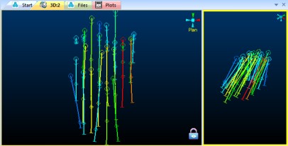
RM showing a locked and freeform view of drillhole data
Your application represents the latest step on this journey; a fully-integrated design and visualization environment that allows you to set up one or more data views in an optimal way for the type of work you are doing. One example could setting up a locked section (which emulates the old Design window behaviour) for digitizing in a plan view, whilst simultaneously viewing the 3D data in another window, rotating it to show the best profile.
Superseding the VR window and Design windows, the 3D window represents the results of thousands of hours of development to ensure that, with your application, you genuinely do get the best design and visualization environments in one window. Due to the formatting requirements for reserve/resource and other mandatory reporting operations, the Plots window has been retained.
In 2016, support was provided for an external 3D window. This was another view, linked to the 3D window, but could be positioned outside of the main application frame. Although some form of clipping customization was added later, this window remains linked to the overlay and scene formatting of the parent.
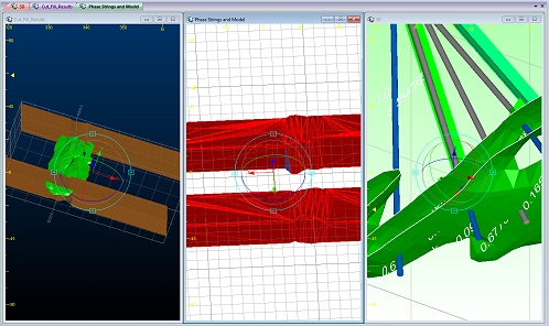
In 2019, 3D window support was given a huge boost with the introduction of independent 3D windows. This facility allows you to create as many independently-configurable 3D windows as you like, available in either embedded and external form. No longer bound to the formatting of the previous window, this provides much more flexibility to how you present your 3D data. The level of independence for each window is generally complete, although all windows still rely on a single 'roster' or loaded data objects (although the overlays that are shown in each window can be completely different).

Multiple independent-embedded 3D
windows
More about independent 3D windows...
Designing in a 3D Window
Designing in a 3D window provides the following advantages:
-
Working in a virtual 3D space (for those users who prefer to work in a virtual environment).
-
Digitizing onto surfaces i.e. Wireframes or Sections, as well as by snapping to point, string and drillhole data.
-
Separate control of multiple sections and views.
-
Everything is updated dynamically - see how that switchback you designed appears in relation to the bench shape, model and topography in full 3D.
-
Viewing data in split windows, multiple floating windows, locked or unlocked.
-
Viewing and editing data in multiple, independently-formatted windows.
|
|
If digitizing strings
with the new-string
command, |
|
|
Controlling double-click behaviour during digitizing You can choose what happens when you double (left) click during digitizing; use a double-click to complete the current command, or enter two digitized points (close to, or coincident with each other). This behaviour is controlled using the Project Options dialog, specifically the Whilst digitizing, you can complete the digitizing operation by double-clicking or double-tapping the final string vertex position. You can also complete the digitizing operation by closing the string. |
Using Sections and Viewpoints during the Design Process
Design commands are generally used in the same way in the 3Dwindow. Any differences in usage are explained in the relevant command's help page by means of additional notes. The main difference when working in these windows however, is the way in which the position and orientation of the working plane i.e. the plane on to which data is digitized when not snapping, and the viewing this working are controlled and used during the design process.
In a 3D window, on the other hand, it is possible to have multiple sections and multiple viewpoints. Multiple sections can be defined and displayed, although only one of them is active at any one time. This active section is referred to as the Current Section. By default, the section named 'Default Section' is automatically selected as the current section; other section types are also available.
The viewpoints and their settings are independent of the sections; only one viewpoint is active and displayed at any one time, this is referred to as the Current Viewpoint. The viewpoint most often used is the 'Floating' viewpoint; other fixed viewpoints can also be defined. More...
It's position and orientation is controlled by using the Navigation toolbar, shown below.
Clipping Data in a 3D Window
By default, a 3D window displays all loaded (and visible) data, using whatever formatting is dictated by each overlay of a 3D object (an object can have multiple overlays).
"Clipping" is the mechanism used to remove visible data from a 3D view, commonly to visualize a cross-section of data in relation to one or more 3D sections. Clipping involves the concept of a clipping plane and a section corridor.
3D Windows Drawing Units
Studio products provide an extensive range of 3D visualization options for 3D overlays in a 3D view. Some options rely on a value to determine the size of a particular item. For example, the width of digitized string data, the size of symbols and dimensions of downhole formatting artefacts, and so on.
Find out more about 3D window drawing units...

How to Design in a 3D Window
The following general methodology is used when designing in the 3D window e.g. digitizing new geological model section strings using drillhole data, generating and manipulating wireframes, designing a mine layout. More detailed procedures for digitizing in the 3D window can be seen here.
-
Select any 3D window.
-
Load and format the reference data e.g. drillholes and fault wireframes, mining outlines and block model.
-
Create a new current object in the Current Objects toolbar.
-
In the Section toolbar, select a current section; change its position and orientation if needed.
-
In the same toolbar, click Align View, to align the view direction orthogonal to the current section. Alternatively, click Lock View to ensure you don't accidentally rotate the view during digitizing (you can unlock the view at any time, but whilst locked, the active section will always be face-on to the camera.
-
In the 3DView toolbar, set the current view to [Floating]; use the zoom buttons to zoom in to the area of interest.
-
Select the design command e.g. new string; digitize the string points.
|
|
Related Topics |
|
|
About
the 3D Window
|

