
Define Report Sections
This is the second of a series of activities relating to field map reporting configuration.
Warning: This topic is intended for Studio Mapper system administrators. You should not attempt any of the following procedures unless you are confident to do so, and are familiar with the concepts described.
Studio Mapper PDF reports are formatted by associating a plot template with at least one map type using the system's system configuration file.
The contents of each projection of a field report is determined by a section definition table, also known as a "section table".
The section definition table contains a description of one or more 3D sections that represent each face in a map. For example, if only a face map is presented, a single 3D section is defined, whereas a full heading comprising face, left wall, right wall and roof will contain four separate records.
An all-purpose file is installed with your application and can be easily adapted for your needs.
The table also defines the clipping distance used, on each side of the face, when viewed orthogonally.
Warning: updating the system configuration file will affect all Studio Mapper projects with which it is associated. Changes should only be made if you are familiar with the XML format, and changes should be tested in an appropriate environment before rolling out to a live system.
To define sections for a FACE mapping report:
A section definition file is used to set up a plot template for reporting. This table supports the automated production of a PDF face map report and requires a specific format. A suitable section definition table is installed with Studio Mapper. This procedure covers copying this file to the right place to be adapted:
-
Launch Studio Mapper and load a project with at least one map.
-
In Windows, browse to your application's installation folder, and the Templates sub-folder. For standard installations, this is here:
C:\Program Files\Datamine\StudioMapper\Templates
-
If one doesn't already exist, in your local database folder, create a folder called "Templates".
-
Copy the file "map_faces.dm" from the software installation Templates folder to your database Templates folder.
-
Adjust the front and back clipping distances for each section as required. There are two ways to do this;
-
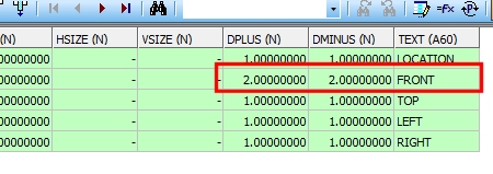
Open the map_faces.dm file in Table Editor and adjust the DPLUS and DMINUS values for each map face projection, e.g. in the table below, each map face projection will be clipped to 1 measurement unit in front and behind the map face apart from the FRONT face which is set to 2 measurement units in front (DPLUS) and behind (DMINUS):
Save the table when all required sections have been updated.
-
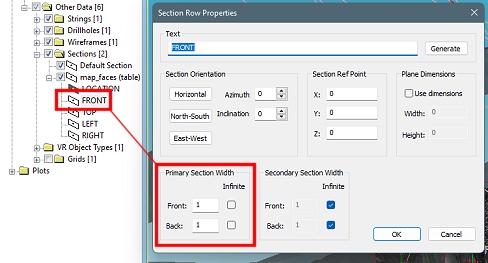
Alternatively, load the table into the Studio Mapper World 3D window and, using the Project Data control bar, expand the 3D | Other Data | Sections folder. Then double-click the map face clipping definition you wish to adjust (e.g. FRONT). This displays the Section Row Properties dialog, allowing you to adjust clipping values:
Once all adjustments (for all map faces) has been made, Save the loaded section definition file, overwriting the one in the active database's Templates folder.Note: the section names are important and are recognized by Studio Mapper. It isn't necessary to delete sections that aren't used in your map. For example, if you are mapping a RIGHT wall only, there is no need to delete the other records.
-
Next, see Configure Dynamic Tables.