|
|
Plane Properties Configuring existing planes |
Plane Properties Dialog
To access this dialog:
-
Double-click a Georeference object in a 3D or Map view node of the Project Data control bar.

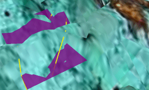
Your application can use strings digitised onto wireframes to specify key planes, for example for joint space analysis. As part of this, a variety of tools and visualization methods are available to help with their generation and interpretation.
For each string, an average plane is calculated which best fits all the points in the string (open or closed). The plane is oriented around its line of true dip, and extents calculated to just fit the source string.
This dialog allows you to format an existing plane, using one of three available tabs:
-
General: set up base properties for the defined plane. More...
-
Associated Files: attach external files to your plane entities. More...
-
Info Mode List: add information to the plane, to be shown when it is right-clicked in the VR window. More...
|
|
The settings described here apply to the currently active 3D window and all linked external windows. Independent windows will be unaffected. |
The General tab of the Planes Properties dialog contains the following fields:
Name: displays the current name of the selected data object overlay.
Source: shows the name of the loaded object from which the current 3D overlay was derived.
Display Type: planes can be viewed as either rectangular or circular shapes.
Color: display legends can either be a standard fixed color, or you can choose to color your data according to a display legend:
Fixed: select this option to use the same color to render your chosen item. Note that this color will also be used to color data that cannot be matched to a legend interval when the Legend option is chosen (see below).
Legend: when this option has been selected, the initial drop-down list in this area can be used to select a predefined legend (system standard or user-created). When a legend has been selected, you will need to select a data field that contains the values to be matched to the legend for display purposes, using the Column drop-down list. Note that only fields relevant to the currently selected object are shown.
As with all legend drop-down lists, once an item has been selected, you can elect to edit the chosen legend or preview it. You can also automatically create a default legend for any selected field:
|
|
Preview the currently selected legend intervals and display properties |
|
|
Edit the currently selected legend using the Legend Manager. |
|
|
Select a default legend for the selected data column if one already exists, or if no default legend is available, the Create New Legend wizard will appear to let you create a new legend. |
Opacity: set the level of opacity/transparency for the selected
plane where 100% is completely opaque and 0% is invisible.
|
|
For more information on viewing a selected plane's data properties, click here. |
|
|
Related Topics |
|
|
The
Planes folder Planes Properties
Dialog - Labels Tab
|


