|
|

Extrude Strings
To access this dialog:
This dialog is shown as part of the Extrude Strings command, and is used to create wireframes from strings extruded in a particular direction.
Before you can use this command, at least one string entity must exist in memory. Note that more than one string can be selected before an extrusion is performed.
Both open and closed strings can be extruded.
Field Details:
Output: you can either create a new wireframe object by extruding strings, or add the created data to the current wireframe object.
Extrusion Direction: specify the direction of the projection using the Azimuth and Dip fields. You can also use one of the preset directions (see below) or a combination of both options.
Extrusion Presets: to set a commonly-used preset direction, the following options are available. Note that the actual direction (backwards or forwards) from the string position is determined by the subsequent Extrusion Distance group (see further below).
-
Up: project with an azimuth of 0 and a dip of -90.
-
View Plane: project the string in a direction perpendicular to the current view direction.
-
Down: project with an azimuth of 0 and a dip of 90.
-
North: project directly northwards, that is, at an Azimuth and Dip of 0.
-
West: project the string with a 270 Azimuth and 0 Dip.
-
East: project the string with a 90 Azimuth and 0 Dip.
-
South: project the string with a 180 Azimuth and 0 Dip
-
VR Section: select any previously defined 3D window section to determine the projection direction.
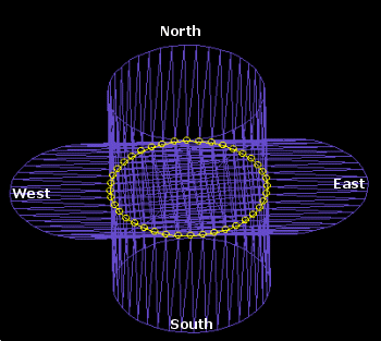
The following images describe the preset directions more graphically. The left hand image shows a closed, circular string, created on the bias between plan and east-west directions. This string has been projected in North, South, East and West directions:
Extrusion Distance: set the distance (either forwards or backwards) to project the selected string(s).
End Link: you can opt to create a 'capped' wireframe using this facility. Select it will create two additional surfaces at each 'end' of the generated object. Note that if multiple strings are projected, the option also exists to treat the strings as separate or otherwise.
Note that the default value for the End Link option is set in the Project Settings dialog under Wireframe Linking | End Link Multiple Strings field.
Note that if an open string is being projected, it is still possible to cap the ends of the resulting wireframe, although the effect will be determined by the overall geometry of the base string - this command will join first and last vertices to create a cap wherever possible.
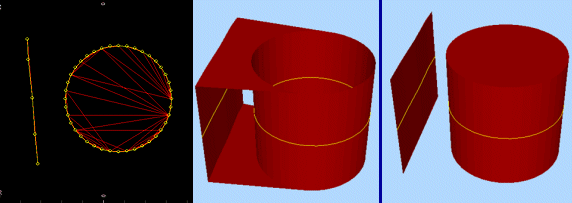
Separate ends: as an example of the Separate Ends option in action, the left image shows the original data used to generate an extrusion (plan view). The central image shows an isometric view of the generated wireframe when ends are capped, but the strings are not treated as separate entities. Compare this with the right-hand image in which the Separate Ends option was enabled:
Wireframe Attributes from strings: if selected, the current attributes held by the original string data will be copied to the resulting wireframe object. If cleared, system default attributes will be used to create the resulting wireframe.