
create-grid-perimeter ("drg")
See this command in the command table.
To access this command:
-
Digitize ribbon >> Tools >> Attributes >> Draw Grid.
-
Using the command line, enter "create-grid-perimeter" and press ENTER.
-
Use the quick key combination "drg"
-
Display the Find Command screen, locate
create-grid-perimeterand click Run.
Command Overview
Generate a grid of closed, rectangular strings in a grid arrangement with (optionally) a unique X and Y attribute for each.
A grid can be defined on any plane (but the result will always be planar, although can be edited afterwards) and each grid rectangle (from now no, referred to as a 'grid unit') can be assigned a incrementing or decrementing X or Y attribute. You get to choose the name of the X and Y attribute if you choose to add one to the output string data.
Command Example
For example, in the image below, grid dimensions were configured as follows:
X Length = 10
X Increments = 3
Y Length = 5
Y Increments = 15
Each grid square is prefixed with "A" for the X value and "B" for the Y value. Each grid unit starts at 1 and increments by 1 in the order it was created:
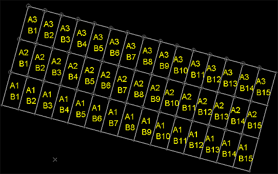
Note that attribute values don't (and aren't supposed to) correspond to coordinate positions, simply the order in which the grid cells were created. With an overall grid Azimuth of 15, the result is:
Tip: Restore previous screen settings using the Restore button to create similar grids to those already generated.
The combination of X and Y grid square attribution, in this case, means each square has a unique grid reference.
Command Steps:
-
Display a 3D window where the origin of your intended grid is visible.
Tip: Whilst it isn't required. it can be useful to either create a 3D section that aligns with your intended grid, or rotate the 3D view so that it is positioned orthogonally (looking down on) the grid you're going to create. Otherwise, you can define the design plane for your grid using any orientation later.
-
Run the command.
The Draw Grid screen displays.
-
Define the Plane on which the grid is generated:
-
Choose a preset plane orientation; either Horizontal, North-South or East-West. The design section aligns with the selected major axis.
-
Extract the Azimuth and Inclination for the selected 3D Section. You can pick any loaded 3D section using the list provided.
-
Choose an arbitrary Azimuth and Inclination.
-
-
Choose the global Parameters for your grid:
-
If you know the coordinates, enter the X, Y and Z values for the bottom left position of your grid (as if viewed from above).
-
Alternatively, Pick any position in any 3D window.
-
-
Enter the Azimuth value used to orient the grid. By default, a grid is generated with zero azimuth.
-
Alternatively, use Pick to select a point in the 3D window from which an Azimuth is derived (based on its comparative position with the origin point).
-
-
-
Enter the Dimensions of the grid units for your grid. X and Y dimensions are both specified in terms of Length and Increments, with the Total Length calculated automatically (which can't be edited). Enter the axis length and number in the specified direction directly into the table.
-
(Optionally) assign Attributes to each grid unit string.
This can be useful for labelling, say, where you have a particular drive layout and wish to annotate the grid using incrementing or decrementing values in each direction. X and Y attributes are set independently but are, essentially, added as a custom attribute to the output string. The values contained in these attributes may or may not relate to coordinate values, or may simply be grid references, unrelated to the world position of the grid unit strings.
For the X and Y attribute (if checked):
-
Choose to enable attribute for the selected 2D axis by either checking X Attribute or Y Attribute (or both).
Once enabled, additional fields become available.
-
Enter the Name of the attribute to add to your output string object. This must adhere to fixed attribute naming conventions for your system.
-
Which grid reference value do you wish to Start from for the selected axis? Enter a number here. This must be a positive integer.
-
How should the grid reference increase for each grid unit? Set in steps of to denote the gap between grid reference values. For example, in a 5 x 5 grid , if one axis should be attributed 1, 2, 3, 4 and 5, the values should Start from "1" and change in steps of "1".
-
If you want attribute values to be applied from the highest first, decrease to the lowest, choose Reverse direction.
-
-
To add a custom Prefix or Suffix to your custom grid reference attribute(s), add the required text. Both are optional.
-
Preview your grid in the 3D window. Data shown at this stage is illustrative only - no object data has been created.
-
Once you are happy with your Preview, choose how to store the output string data:
-
To store the grid data in the current string object, choose Current Object. Grid data is added to whatever data is already there.
-
Choose an existing, or specify a new data Object in which to store the grid.
-
-
Click Save to generate grid data as specified.
Related topics and activities