
link-boundary ("lbo")
See this command in the command table.
To access this command:
-
Wireframe Design ribbon >> Create >> Link >> Boundary.
-
Using the command line, enter "link-boundary" and press ENTER.
-
Use the quick key combination "lbo".
-
Display the Find Command screen, locate
link-boundaryand click Run.
Command Overview
Create a wireframe link between two perimeters (closed strings) honouring any boundary and bridge strings. You can also link multiple perimeters when creating bifurcated or split wireframes.
Note: a bridge string is a string that has both its first and last points connected to points on one of the two strings which are to be linked. It is not necessary to select a bridge string, as these are automatically detected during the linking process.
-
At least one of the two strings selected for linking must have at least one bridge string connected to it.
-
More than one bridge string may be connected to a string for linking.
-
If the line is specified with the minimum number of points, then additional points be can generated in the link with the new point separation (dtm-new-point-separation) command to improve the triangle shape.
-
The tag or boundary or bridge strings must have their end points snapped (point or line) to a perimeter.
-
Bridge strings can contain any number of points and be fully three dimensional, but their end points must be connected to points on one of the selected strings. Crossovers of bridge strings should be avoided. The bridge strings themselves are not selected when running this command, they are automatically detected.
-
The links take their colour from the first string of each string-pair used for the linking.
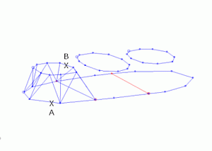
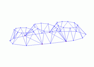
Link Boundary Example
In the example below, the bottom perimeter is linked to the top perimeters, using the link-boundary command, honoring the red boundary strings:
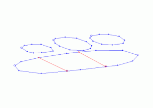
Each portion of the lower perimeter is linked to the corresponding perimeter in the top i.e. the perimeters are selected in pairs:
The remaining two bifurcations are linked in the same way:
Using the 3D Solid linking method
If you have strings on adjacent sections that are to be linked together, and those strings cross each other when viewed in the direction of wireframing, then temporary vertices are inserted into the string and these temporary vertices are used when the wireframe is created. Since pairs of strings are wireframed at a time it is possible for these temporary vertices to be created for one pair of strings and not the other. In this situation a wireframe may be built which contains inconsistencies.
Therefore, the 3D-Solid method is not suitable for use with the older linking commands if adjacent sections contain strings that cross each other in the direction of wireframing.
Command steps:
-
To preserve existing wireframe data, in the Current Objects toolbar, select or create a new current wireframe object. Alternatively, add wireframe data to the current wireframe object.
Note: if no wireframe object exists yet, a new one is created automatically by this command.
-
Load perimeter strings.
-
Run the link-boundary command.
-
Following the prompts in the Status Bar, select a first point on a perimeter (the one which has associated boundary or bridge strings).
-
Select a second perimeter.
-
Click Cancel to complete the command.
-
Link the remaining perimeters or strings using the related link-boundary-to-line, end-link-boundary or other string linking commands.
Related topics and activities