|
|
Pit Design Tutorial - Benches and DTMs Defining initial pit parameters for design tasks |

Pit Design Tutorial - Define Model, Benches and DTM
You have already defined your pit name and a surface topography.
The following exercises will take you through the minimum required setup to allow pit design data to be generated around information stored in the Reserves Database. The information you will define is:
-
An input planning model and field assignments
-
An initial definition for a pit phase
This will generate a pit design (with integrated road network) that can be used as the starting point for mining block generation and an updated reserves evaluation.
Prerequisites
-
You have completed Project Setup
Exercise: Define Model
- To define a planning model select Model | Define from the Setup ribbon.
- Click Add
and browse to C:\Database\DMTutorials\Data\VBOP\Datamineagain. This time select _vb_npvmod1.dm
and clickOpen,
then OK to list it on
the Define Planning Model
panel.
Important fields are detected automatically and listed in the table below")
Adding a model will copy the target file to the current project folders 'OPDatabase' folder. This allows the project to be archived/ported in future. As such, changes to the model in the initial folder (i.e. the original source) will not affect your OP project.
- Studio OP's design tools, such as Generate
Contours, require there to be at least one attribute containing
phase information (in the example model specified above, this
information is contained within the PHASE field).
To allow planning model attribute data to be used in subsequent tasks, they must be assigned as either an "Optimised Phase", "Mining Phase" or "LG Phase".
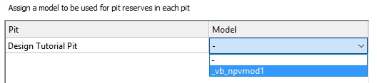
In this example, change the PHASE field to the "Optimised Phase" field assignment. - Assign this model to your pit using the drop-down
list at the bottom of the panel:
- Save and Close the panel. At this point, the remaining model setup icons become available.
Exercise: Validate Model
It's important to make sure your planning model doesn't contain unexpected data such as absent or negative grade data. The Validate Model task is used to make important checks to ensure your model data can be used effectively in subsequent pit design and reserves calculation tasks.
- Select Model | Validate. It can take a few seconds for the panel to appear with validation results.
- Studio OP automatically analyses the assigned planning model and, for numeric fields other than system defaults will check for and report any absent or negative values. You are also given a chance to automatically resolve these conflicts.
- In this case, there are no conflicts or
unexpected data (i.e. there are no absent or negative values in
key fields) so Save and Close
the task.
The Validate Model task uses Studio's STATS process.
Exercise: Define Attributes
One of the primary functions of a digital pit design is that it allows you to evaluate reserves implied by the input planning model.
Studio OP also allows you to enhanced your input model with additional attributes that will be used during the reporting of reserves later on. You can define the attributes values using either direct data input, using constant values and/or a filter.
For example, you could create a production flow attribute to ensure that only blocks that meet a specific production cost criterion are scheduled (in this case, only blocks that have a zero PCOST will qualify for scheduling).
- Select Model | Attributes.
- The [_vb_npvmod1] model is already selected in the Planning model drop-down list.
- No additional attributes have been defined so click New to get started.
- A new entry is added to the attribute table. The default name is ATTR_1 - click in the Name field to replace this with "PFLOW". This is an alphanumeric attribute that will determine if a block is to be scheduled.
- Select [Alphanumeric] using the Type drop-down list.
- The default Length (8) is fine.
- The attribute will be reported as part of the reserves calculation later, so select [Dominant] from the Evaluate drop-down list.
- Weight is not relevant for this attribute.
- Enter the following Description: "Determines test for scheduling based on grade and PCOST"
- Click Save (not Save and Close).
- Select the Values tab.
- Click New to add a new entry to the values table.
- If you were going to set a static value for PFLOW, you would
select it using the Attribute
drop-down list and assign it a value directly. However - in this
example, you're going to define an expression that explicitly
states how the PFLOW attribute will be defined. As the expression
contains both the attribute name and the modification instruction,
there is no need to select the attribute as all the information
will be provided.
As such, make sure the Attribute field lists "-". - You're going to define PFLOW values in the input model based on the status of the existing PCOST attribute. Use the Value list to select <new named value>.
- In the Attribute Value group of controls below the main table, click Edit to display the Attribute Value Editor dialog.
- Enter the following expression in the Expression
field at the top of the dialog:
if (PCOST==0)
PFLOW="All"
end - Click Test. You will see a message stating that the current model is already loaded, so cannot be edited. Click Yes.
- Click Test again and you will see the Status "The expression is valid" click OK to return to the Values panel.
- At this point, the expression is tested, but the attribute has not yet been added to the model file with the conditional values. Click Run to update the model.
- Click Save and Close to close the Model Attributes task. Your model now includes a new attribute (PFLOW) with the value "All" where PCOST is zero, which happens to be the majority of the records in the file.
Exercise: Define Phases
In this tutorial, you will create a set of contour strings around isoshells based around phase values in the planning model. These strings will subsequently be used as constraint strings in pit design and road definition. The "phases" of the model need to be defined so that they can (optionally) be interrogated to produce an isoshell surface which acts as a canvas for shell contours.
This exercise will show you how to add a series of shells to the OP database and make them available for selection during contour, road definition and automatic design functions later on.
Phases can either be defined manually (you explicitly name the phase, shell and model value to which the description refers) or you can automatically create phases; one for each unique value in the planning model PHASE attribute.
For this example, you're going to create a phase that represents each of the distinct PHASE values in the input planning model - the automatic method..
- Select Phases | Define.
- Select theUse Model radio button on the right of the screen. ClickYesto confirm.
- ClickInitializeto populate the table with 31 separate phase descriptions. In this tutorial, you will design a pit around the first two phases only.
- Click Save and Close.
Exercise: Define Benches
- If not already selected, select the Reserves ribbon and Benches | Define.
- In this tutorial, you will use the dimensions
of the input model to define the benches for your pit (another
option would be to extract information from an imported string
file, manually set elevation values and heights or to use imported
3D surfaces.
Select the From planning model option (note that _vb_npvmod1 is already displayed). - Click Apply.
A set of 17 benches will be defined, each with a 20m bench height, encompassing the full hull of the input model.
By default, the bench identifier (the Label) will be the crest elevation. This can be changed but is suitable for this tutorial. - Save and Close the task.