|
|
Pit Design Tutorial - Ramp Layout Defining your in-pit network |

Pit Design Tutorial - Ramp Layout
The Ramp Layout task allows road strings to be rapidly created on top of a dtm wireframe, which would typically be a pit shell. The Generate Ramp Layout task will allow road start points and target end elevations to be changed automatically, and will then recalculate the profile of the road, climbing at the requested elevation around the pit until it reaches the target elevation.
In this section, you'll create a set of simple road rules, including switchbacks, to be used in the automatic pit design task.
For clarity, each pit shell is colored red in these examples. The default color for generated phase DTMs is grey.
Prerequisites
-
You have completed Create Phase Contours.
Exercise: Generate Road Definition using Phase 1 Shell
In this exercise, you will create a single road network originating at the pit base and rising upwards, anticlockwise with a maximum gradient of 15 degrees. There will be a switchback at (approximately) the 100m elevation.
- Using the Design ribbon, select Ramp Layout.
- Use the Phase drop-down list to select [P1_PH1]. You'll see that the list only has 2 options; one for each phase that is supported by a Shell DTM.
- In the New Road section, enter "Road1" into the Name field.
- Set the Gradient to "15" [degrees] [Up]
- Set a road Width of "10" (this should be the default value).
- Ensure the Clockwise radio button is selected.
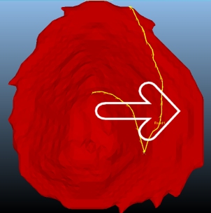
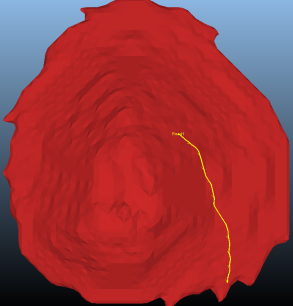
- Click Choose
Start Point and right-click (approximately) in the position
shown below:
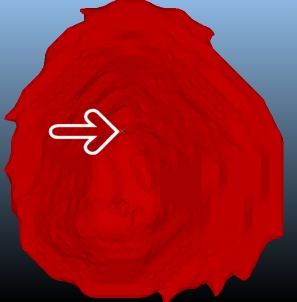
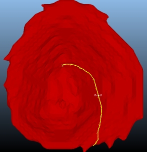
- A road is generated automatically:
- Click Move Start (this is found slightly further down the dialog) and left-click other start positions around the shell - aim to make your clicks at roughly the same elevation as the first.
- Return the road to a similar state as it started. For each version of the road, the rising gradient is set at 15 degrees (although you can't see the road width in this previewing task, it will be used in the Auto Design task later).
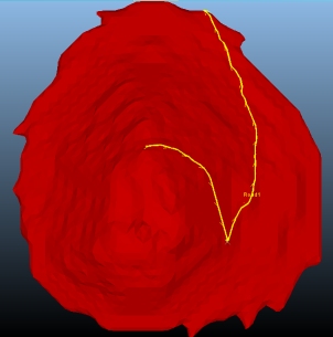
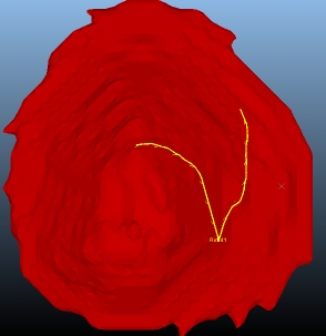
- Click Add
Switchback and left-click approximately in the location
shown:
- A switchback is formed:
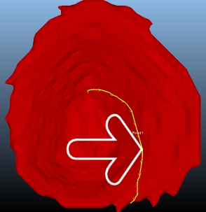
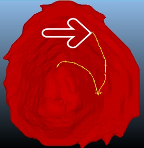
- Next, click Move
End Elevation and left-click in the location shown:
- The end elevation of the string is move
to meet the elevation below the cursor - the important point is
that you cannot set the actual location of the end of the string
without (potentially) adjusting the maximum road gradient and/or
starting point. To honor these constraints, only the terminal
elevation can be set:
- In cases where a road exit point is important
(say, to honor a pit exit), you can set it precisely by reversing
the road and making it the start point.
As an example, click Reverse Road (the arrow directions will change). - Now click Move
Start and left-click in the location shown below:
Note that the start position has been adjusted to accommodate a non-negotiable gradient value. - Reverse the road again so it starts at the pit base. It's useful to use this combination of road reversal and move commands. Note that the gradient will be honored in all cases, and must be specified in advance (as it's an operationally important aspect of mine design, Studio open pits are designed to honor the gradient, allowing you to flex either the start or end position as required.
- Move the start of the road so it is positioned
here (you're moving it out of the bottom of the shell and into
an area that will line up with the pit base that will be defined
in the Auto Design task:
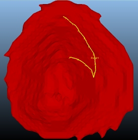
Try left-clicking and holding the mouse button to dynamically position the road with mouse movement - this can make fine-tuning a lot easier! - Finally, click Remove
Switchback and right-click in the switchback position to
revert the road:
- You can generate as many roads as you wish, but this example only requires one.Save and Close your task.