
Auto Design - Berm Tapering
To access this task:
-
Activate the Design ribbon and select Pit Modelling >> Auto Design. Select the Berm Tapering tab.
-
Activate the Design ribbon and select Dump Modelling >> Auto Design. Select the Berm Tapering tab.
Note: All settings on this panel relate to the active pit design scenario only. Specified tapering values are stored per-phase; your settings can be independently configured for each phase of your pit or dump.
The principles described below apply to both pit and dump automated design tasks.
This panel is used to control how (or if) berm tapering is applied, either throughout the pit or dump or for individual benches or lifts. Default settings are set, which are used unless a more specific constraint (at the bench or lift level) is detected.
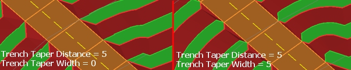
Berm tapering gradually reduces the width of the berm where the berm meets the road in a pit or dump design. A taper can be applied on either the inside or outside of the road, and you can also specify the length of berm over which the width of the berm will be reduced on the specified side of the road.
Berm Tapering Examples
A road with non-zero inside and outside taper distances:
The same data with
zero taper distances set both inside and outside
The distance over which a taper is applied can have a dramatic effect on not only the road formation, but also how the design above a road is adjusted in order to accommodate the new settings.
For example; consider an automated design where each road segment is approximately 200m in length. The default berm taper distance is 100m, meaning that the start of the taper has 100m in which to reach the full berm width. With automatic projections, this can give rise to a 'stepped' effect as the road rapidly reaches its target berm width over 50% of the road segment length, continuing at that width for another 100m then projecting rapidly out again, e.g.:
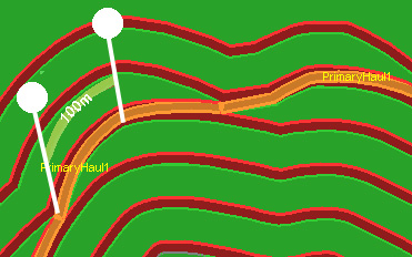
As the design data above the road has to be adjusted to fit in this adjustment over a relatively short distance, the toe and crest strings at higher benches are progressively pushed outwards (pit) or inwards (dump).
By adjusting the inner and outer taper distances to 200m (approximately the full length of each road segment), there is a smoother progression with few extreme changes in road direction:
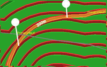
It can be useful to check the length of a road segment with query-string, then adjust the pit either generally, or for one or more benches in order to create a practical road network layout.
Note: Tapering is not applied to the berm that sits on the target End Elevation.
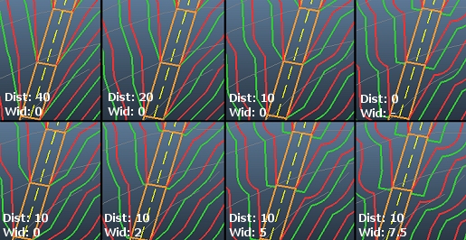
Taper Distance Examples
More examples, showing decreasing taper distance on the top row (vs. a static width) and increasing width on the bottom row:
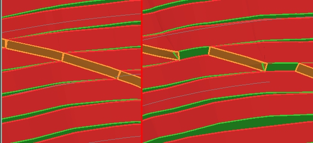
Flat Road Distance Example
Flat Road Distance is the distance a road will progress along each berm before it progresses upwards or downwards using the specified gradient. For example, in the image below, a Flat Road Distance of zero is shown on the left and a 20m distance is shown on the right. You can see how each road segment is fragmented, allowing the berm to serve as the road for a given distance before continuing its ascent or descent.
To configure berm taping for your pit or dump scenario:
-
Select the adaptive road to be subject to berm tapering constraints by expanding the Select Road list. Adaptive roads are configured using either the Auto Pit Design or Dynamic Dump Design screens.
Alternatively, to define tapering settings for all roads (where a road-specific override hasn't been specified already, choose Default.
-
Configure the berm tapering table by:
-
Manually entering per-bench or per-lift tapering constraints into the table.
-
Setting up a rule to automatically populate the table using a pattern of instructions.
-
A combination of rule-based and manual methods.
To define a rule to update the table according to general constraints:
-
Choose the bench or lift range within which tapering constraints apply. Do this by setting the From bench (or lift) and To bench (or lift) fields, which are inclusive. For example, in open pit design, to apply conditioning values from bench 900 to 800 inclusive, enter "900" and "800" accordingly.
Note: Open pit bench ranges are defined according to increasing depth, between the uppermost (From bench) and lowest (To bench) values. The opposite is true for dump design, where a range should be specified in dump lift order, from lowest to highest elevation.
-
Choose the frequency, within the specified range, that conditioning values are applied. For example, to define values for every other bench, set constraints every 2 benches, set 1. Defining a periodic constraint can be useful where it is known that a catch bench exists at regular intervals either down the pit or up the dump.
-
Choose the conditioning control to be updated. This can be one of the following, which matches the available columns in the table below:
-
Inside Taper Distance - this setting can only be applied if an adaptive road is selected.
-
Inside Taper Width - adaptive roads only.
-
Outside Taper Distance - adaptive roads only.
-
Outside Taper Width - adaptive roads only.
-
Fixed Road Taper Distance - only accessible if the Default road is active and applies to all fixed roads of the scenario.
-
Fixed Road Taper Width - only accessible if the Default road is active. Fixed roads only.
-
Flat Road Distance - adaptive roads only.
These constraint types are described in more detail further below.
Tip: Apply rule-based tapering constraints cumulatively to the table. For example, you can set the Inside Taper Distance, then apply an Outside Taper Distance by Applying each configuration successively.
-
-
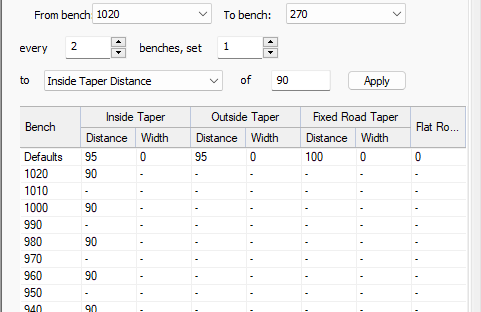
Define the actual constraint value using the of field.
-
Apply the rule to the table below. For example, if an Inside Taper Distance of 90 is applied to each alternate bench from 1020 to 270 elevation, with no prior constraints applied, the table looks like this:
-
-
To manually edit the berm tapering constraints table:
-
Review the Defaults table row. These tapering values are applied for all benches or lifts where a more specific constraint has not been set (that is, where a "-" appears in the table below). You can adjust any of the following default values:
-
Inside / Outside Taper Distance: Specify the inside or outside distance over which the width of the berm will be reduced on the specified side of the adaptive road.
If zero is specified, default taper width field(s) (see below) are disabled.
-
Inside / Outside Taper Width: The offset to be applied to the end of the adaptive road (at the taper point). This field is disabled if the associated taper distance is zero.
-
Fixed Road Taper Distance: A taper distance (applied to both sides of a fixed road) over which the berm is reduced.
-
Fixed Road Taper Width: this is the offset that can be applied to the end of the fixed road at the taper point. For example:
More examples, showing decreasing taper distance on the top row (vs. a static width) and increasing width on the bottom row:
-
Flat Road Distance: the distance a road will progress along each berm before it progresses upwards or downwards (depending on the design order of the pit or dump) using the specified gradient. For example, in the image below, a Flat Road Distance of zero is shown on the left and a 20m distance is shown on the right. You can see how each road segment is fragmented, allowing the berm to serve as the road for a given distance before continuing its ascent/descent.
-
-
Related topics and activities