
Define Slope Regions

For an open pit mine or dump, the design of the slopes is one of the major challenges at every stage of planning and operation. It requires specialised knowledge of the geology, which is often complex in the vicinity of orebodies where structure and/or alteration may be key factors, and of the material properties, which are frequently highly variable. It also requires an understanding of the practical aspects of design implementation.
The aim of any open pit mine design is to provide an optimal excavation configuration in the context of safety, ore recovery and financial return. Similarly, when designing dumps, regional and/or rosette control should be designed to ensure each dump is both safe and practical. Both scenarios, ultimately, utilize slope and width control to ensure a digital draft is achievable and meets operational requirements.
In your application, slope regions are defined firstly at the DEFAULT level. The slope specifications (face angle, berm width, catch bench width) will be applied if no other, more granular constraints are defined.
Regional slope constraints can be defined too using one of multiple methods (manually, based on planning model data or from imported strings).
At the lowest level, you can define slope regions using located 'rosettes'. You can find out more about rosettes below.
You can also define bench-specific overrides (providing benches have been defined), which will override more general settings at the region or default level.
Finally, as a way of supporting variable bench heights within the same bench, you can also define "bench fallbacks". This allows you to determine what the default behaviour is (per-bench) where

As with all managed tasks, updates made on this panel are committed to your project using the Save (1) or Save and Close (2) buttons at the top of the form. You can also Close without saving (3).
Rosettes
Slope regions can optionally include one or more rosettes. Rosettes comprise a location and a set of azimuths each of which has a set of the three standard control values (face angle, standard and catch berm widths).
Rosettes have a minimum and maximum elevation to define their volume of influence. The horizontal influence of a rosette covers the entire slope region in which it is contained.
Each rosette is given an X, Y location. The X, Y location is only used when multiple rosettes are being used to interpolate the projection values a string point.
How Rosettes Work
When using a single rosette to determine the projection control values at a point, the direction azimuth of the projection is used to locate the corresponding azimuth in the rosette. The X,Y location of the rosette is NOT used. The elevation constraints are always used.
In the diagram below a circle is being projected using the rosette parameters in the table. If a point is being projected at an azimuth of exactly 0⁰ the berm width is 10. If a point is projected at an azimuth of 220⁰ the berm width is 30.
There is a gradual change in berm widths between the specified azimuths. If a point is being projected at 290⁰ the berm width will be 15, i.e. mid-way between 0 and 30.
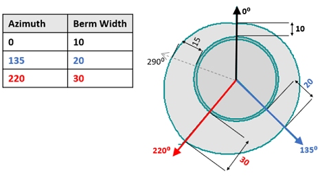
Face angle values are determined using the same methodology for berm widths as described above.
Multiple Rosettes and Interpolation of Control Values
For pits or dumps in more advanced stages of design it is common for slope regions to contain at least one rosette, for example to force temporary internal walls to have a shallower angle than final walls which due to their longevity warrant the extra cost of being blasted using pre-splitting.
For more complex geotechnical configurations, or perhaps in an early study using a single default slope region, multiple rosettes may be used. In this case an interpolated value at a projection point is calculated by using each of the relevant rosette values.
The influence of each rosette can be adjusted by assigning it an inverse distance weighting (IDW Power value) which is used in the interpolation. If no IDW Power value is assigned then nearest neighbour interpolation is used.
Rosettes Reminders
- The X,Y location of a rosette is only relevant when interpolating values from multiple rosettes.
- The direction of projection of a point is used to determine the corresponding rosette azimuth values. A single point on a design string may have up to 2 projection directions: one for each of the adjacent edges.
- The X,Y location of a rosette may be outside the volume of the slope region in which it is being used.
- Each rosette belongs to a single slope region
Defining Regions and Rosettes
Region and rosette configuration is performed per-pit or per-dump. Whilst pits are defined using the Manage task (Setup ribbon), dumps are defined using the Define Dumps task. Once defined, they are selectable using the appropriate Define Slopes task (Design ribbon); one exists for pits and one for dumps. Depending on how you accessed the task, either pits or dumps will be selectable, never both.
- Pits are selected using the Pit menu.
- Dumps are selected using the Dump menu.
Regions can (optionally) be supported by one or more rosettes. A rosette is defined for a given elevation range (from Z to Z), with independent face angle and berm width settings for each rosette being nominated to a given azimuth range. A rosette is located using an XY coordinate, and multiple rosettes can influence a face angle within a region.
For each region (and if specified, for each rosette within a region) you can define both a standard (Normal) and Catch bench (also known as a safety berm or geotechnical berm - in essence it is a wide berm designed to catch rockfall and slip), allowing each region to be associated with a particular berm type (using the Bench Constraints panel - see further below).
There are two panels for setting up your region and rosette definitions for your pit or dump:
- Define Regions—define region and rosette information for your pit. Define the spatial reference for your slope region using one of the following methods:
- Manually, using the tables provided.
-
Extract from the input model (pit slope regions only, this is not an available option for dump region definition). If using a planning model or boundary strings to define regions, an attribute within the selected file will be used to populate a table definition containing region information.
The geological model presents a 3D distribution of the material types that will be involved in the pit walls. The material type categories can relate not only to lithology but also to the degree and type of alteration, which can significantly change material properties, either positively (silicification) or negatively (argillisation)
-
Use boundary strings. Define each region and default values, then any additional width and angle specifications (per region) using rosette definitions.
-
Bench/Lift Constraints—define rules, per-bench/lift or contiguous group of benches/lifts.
For pit regions, you can select a bench from those already defined as part of the Define Benches task - Reserves ribbon). For dump regions, the available lifts are as defined using the Define Dumps task.
For example, you can define pit slopes using logic such as "after every 2 benches, set a berm width to 18m but for every successive 4th bench, set a catch bench of 25m other than for benches 2120m and 2130m as they require a 30m bench and 20 degree face angle".Using this panel, you can also define slopes on a bench-by-bench basis, regardless of the pit default, region default or "nth bench" constraints. Define for any bench reference, whether a berm exists and if so, whether it is a standard or catch bench. Each bench can be assigned a previously defined region/rosette configuration and, if required, you can even set a manual override of face angle and berm width.
Tip: Slope region boundary strings can be shown when designing pits and dumps with the automated tasks.
Related topics and activities