|
|
Defining Mine Design Settings Specifying the open pit design settings for your project. |

Overview
In this portion of the tutorial you are going to define conventions, general interface and project settings that are typically used during the open pit design process.
Prerequisites
Required:
-
Created a new project and added all the required tutorial files i.e. the exercises on the Creating a New Project page.
Links to exercises
The following exercises are available on this page:
Exercise: Defining Project Settings
In this exercise you are going to define the following project settings:
-
default string point symbol size
-
evaluation control settings.
-
a 3D window grid
-
a white 3D window background
Setting a Default Symbol Size for Displayed Data
-
Activate the Home ribbon and select Project | Settings to display the Project Settings dialog.
-
In the Project Settings dialog, select the Data Display tab.
-
In the right pane, Symbols group, use the Default symbol size: spin buttons to define a value of '2' mm.
-
Leave the Project Settings dialog open.
-
Click Apply.
Evaluation Control Settings
-
Still in theProject Settingsdialog, select theMine Design tab
-
In the right pane, Evaluation Control group, select the Evaluate Block Model option.
-
Ensure the following check boxes are disabled:
-
Full cell evaluation
-
Use Display Legend
")
-
Clearing the Full cell evaluation check box allows the evaluation commands to run a partial cell evaluation i.e. the portions of block model cells falling outside the evaluated strings or wireframes do not form part of the evaluation. This allows a more accurate evaluation to be done, but is also generally slower.
-
The default selected item in the Legend drop-down list is used for now, as an evaluation legend will be defined in a later exercise.
-
-
-
Click OK to dismiss the Project Settings dialog.
Design Window Display Grid Settings
-
Activate the 3D window.
-
Display the Sheets control bar.
-
Expand the Grids folder and double click the [Default Grid] option.
-
In the Format toolbar, click Grids.
-
In the Format Display dialog, Grids tab, select the Default grid and define the following settings:
-
Fixed intervals: enable this check box and set a fix value of "10" for X, Y and Z.
-
Major line every N: set this to "20"
-
Close the Default Grid Properties dialog.
Exercise: Defining Mine Design Settings
In this exercise you are going to define the mine design settings:
-
metric units
-
gradient convention to 1:N and positive up
-
face angle
-
berm width.
Measurement Unit Settings
All dimensions given in this tutorial are based on metric units.
-
To ensure your system is in this mode, access the Home ribbons Project | Options button.
-
In theOptionsdialog, select theData - General tab.
-
SetDrawing UnitstoMetric (mm)
-
SetData UnitstoMetric (m).
-
ClickOK.
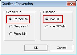
Setting Gradient Convention
-
Activate the Format ribbon and select General | Gradient.
-
In the Gradient Convention dialog, select the Gradient In option Percent %.
-
Select the Direction option +ve UP, click OK.
Setting the Road, Berm and Contour Colours
-
Activate the Design ribbon.
-
Select Design | Set Colors | Road.
-
In the Studio OP dialog, check that the color is set to '5.0' i.e. green, click OK.
-
Select Design | Set Colors | Berm.
-
In the Studio OP dialog, check that the color is set to '3.0' i.e. orange, click OK.
-
Select Design | Set Colors | Contour.
-
In the Studio OP dialog, check that the color is set to '4.0' i.e. yellow, click OK.
Setting the Face Angle and Berm Width
-
Using the Design ribbon, select Design | Face Angle.
-
In the Studio OP dialog, check that the default face angle is '60' degrees, click OK.
In Studio's pit design tools, road gradients are expressed as percent and face angles are in degrees.
-
Select Design | Berm Width.
-
In the Studio OP dialog, set the berm width to '8' m, click OK.
-
Select File | Save.
Copyright © Datamine Corporate Limited
JMN 20048_00_EN