
Outline Design Segmentation Examples
Your application subdivides design solids (derived from either fixed cross-section, outline, complex solid or wireframe data) into activities by subdivision. How design files are processed depends on their respect design definitions.
Each subdivided block of data (essentially, a closed wireframe volume) represents an activity for dependency definition and, ultimately, extraction scheduling.
This topic focusses on how the outline design shapes (OUT) are segmented during processing. References are made to fields throughout and some previous knowledge is assumed. These fields are described in detail here.
Outline Segmentation Methods
Essentially, two methods of outline segmentation are available on the OUT Design Definitions panel; Centreline and Bounding Box. In more detail:
-
A calculated Centreline thoughout the outline polygon. This is an automatically calculated centreline that will attempt to mimic the direction of mining from the start point of the activity to the end.
Outline shapes are varied, and in cases where a centreline is easily implied, this is generally the most suitable option. With this method, the azimuth of the subdivided block walls can either be orthogonal to the centreline (and potentially variable), fixed to a particular azimuth or read from the OUT design string file. This method may be suitable for outline shapes where a centreline is obvious, e.g. without severe kinks or pinch points which may make a centreline calculation ambiguous.
- A Bounding Box. This method works by rotating a given outline by the segmenting azimuth, and then taking the axis aligned bounding box's extents in the Y direction to produce a reference line that must extend across the entire outline, the reference line is then rotated back to the original system. We then have a reference line that extends exactly across the entire outline at the given azimuth (like map callipers). The segmenting then proceeds in a similar manner to the [Centreline] method using that reference line.
Centreline Method
Considering the Centreline method, the following shows the same OUT design shape segmented with this method. The only difference between the three images is in the Direction setting, which can be either [Calculated], meaning an activity wall will be angled orthogonally to the centreline that represents the 'best fit' centreline for the shape, or according to a [Defined Azimuth], which forces all walls to align with the same azimuth, regardless of the centreline shape at each point and [Dynamic Azimuth] whereby azimuth values are read from an attribute in the OUT design file:
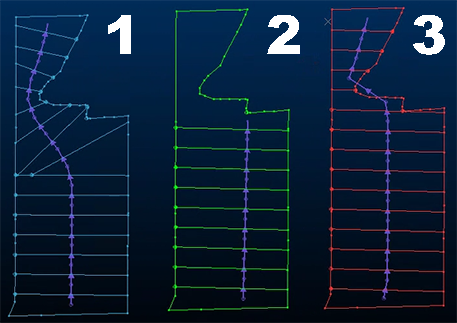
(Dependency arrows are also shown in purple)
-
In the first image, the Calculated direction, whilst it causes the outline polygon to be fully-segmented, does not represent realistic extraction activities; the varying azimuth around the pinch point wouldn't generally be expected in real life.
-
The second image uses a Defined Azimuth approach but this causes the centreline to terminate early, resulting in an arbitrarily large volume for the final block of the volume. This too isn't a practical outcome.
-
The third image represents an outcome where azimuth values are read from the OUT design string file (Dynamic Azimuth option). This ensures that the OUT polygon is sensibly segmented, but does require upfront effort to ensure the input design file includes the relevant azimuth information. Therefore, the outcome is sensible, but requires more advance design and file preparation.
Bounding Box Method
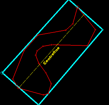
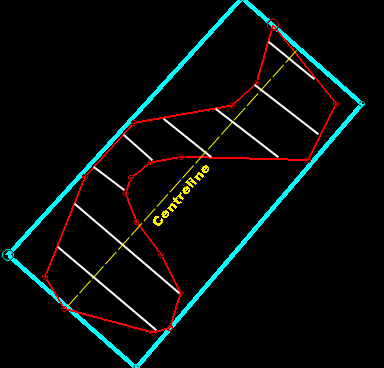
The Bounding Box method can be used to set up a consistent azimuth throughout the OUT polygon. This is achieved by wrapping a bounding box at a given azimuth value around the minimum and maximum extents of the polygonal shape.
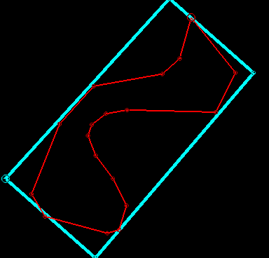
For example, the OUT polygon below (in red) would provide a challenge for either the [Calculated] or [Defined Azimuth] centreline segmentation method options, but if a bounding box is used to create a centreline, the polygon can be fully segmented automatically, in a realistic manner:
The [Bounding Box] method can be controlled using a Defined Azimuth or a Dynamic Azimuth direction.
Related topics and activities