
Outline Design Type
Outlines are projected vertically by a specified distance to create a 3D excavation. These are similar in property to a Fixed cross-sectional shape in that their profile is constant, but with outlines, the projection is made from a closed string
All outline strings must be 'closed', meaning the end point and start point are the same. The Outlines tab in the Design Definitions menu enables you to enter properties for the outline design strings.
You can access generic data management functions throughout the design definition process.
Once processed, outline solids will be generated as an in-memory wireframe object called "OUT Solids", which can be accessed using the Sheets control bar. This can be useful for visualizing/animating the resulting object to review the calculated segmentation and sequencing. A corresponding points file is also generated, which represents the location that will become the "activity" point for each segment.
Advanced extrusion controls are also available for more complex outline design solids. See Process Data Changes.

Example of extruded outline solids in Studio UG
Design Definition Controls
You can add a new definition using the + icon at the top right of the panel. You can also copy an existing definition and edit it if you wish. The same button group also contains a delete definition button, but this is only possible if the definition is not locked (i.e. it hasn't already been subject to processing).

- Add a definition.
- Copy the selected activity definition to a new definition.
- Display the Bulk Field Change screen to make wholesale changes to all selected definitions (at least 2 definitions must be selected in the upper table.
- Delete the selected definitions.
Defining Outline Design Items
Design types are defined using a combination of the following panels:
- Apply Design Definitions: apply previously-defined design definitions to your design data.
- Edit Design Definitions: edit, create and delete design definitions for FXS, CXS, OUT and WFM types.
- Generate Design Definitions: if you choose to create design definitions based on information in an existing physical file, use this to select a grouping field and extract the required properties.
- Edit FXS Shapes: create your cross sectional shape, or edit an existing one. Only used for Fixed Cross-sectional design type definitions.
- Edit Default Values: set up default value sets that can be applied to one or more definitions.
These panels can be opened whilst another panel is currently displayed; handy for setting up default values, shapes and definitions, then applying them quickly.
The default Density that you wish to use for each design type must be pre-configured using the Edit Default Values panel.
Matching Attributes
In versions prior to version 2.1, Studio UG matched designs to definitions by the field DESIGNDF (the design definition Name). In these versions, you had to ensure you applied the design definition to your designs. Applying a design definition to a design would set the values of the DESIGNDF, COLOUR, LSTYLE, and SYMBOL columns. During processing, the design definition of a design was only matched by reading the values in the DESIGNDF column. This could lead to a mismatch between the value of DESIGNDF and the display Properties (COLOUR, LSTYLE, SYMBOL) if you modified the display properties of your designs without using the Apply Design Definitions feature. In effect, there was a risk of data duplication that could get out of sync.
In Studio UG version 2.1 and later designs are once again matched to design definitions by matching attribute values. This means that if the attribute values are on the design, you don't need to apply the design definition as it will automatically be matched during processing. The action of applying a design definition sets the matching attribute values on the designs so that the automatic matching will work. This provides more flexibility and can save significant amounts of time. If the designs already have the appropriate attribute values, you can jump straight to processing. To apply values to the matching attributes, you can use the Apply Design Definitions screen, standard Studio commands, or even use a script.
You can select one or more attribute definitions to use for matching. Each design definition must have a unique combination of values for the matching attributes. The matching attribute definitions are defined per design type. You can still match using the display properties (LSTYLE, COLOUR, SYMBOL), but you are no longer restricted to doing so. Matching on fields other than the display properties allows you to use the same design definition for designs that have different colours, for example. Activity Solids get their colour from their associated design, whether COLOUR is used in the attribute matching or not.
In a way this is how Studio 5D Planner worked: it was just hard-coded to match by the attributes COLOUR, LSTYLE, and SYMBOL. In Studio UG, this restriction is lifted.
Each design type must match on at least one attribute. You can choose to match on the system attributes COLOUR, LSTYLE, and SYMBOL or any of the user attributes. The design definition needs a unique name as well.
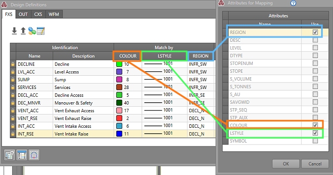
These "Match By" attributes are configured using the Attributes for Mapping panel, a simple field chooser that updates (and is synchronized with) the Edit Design Definitions table.
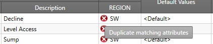
If it is not possible to create unique combinations of matching attributes for existing definitions, non-unique value combinations will be highlighted in the definitions table, for example:
The Solid colour will be taken from the design file, regardless of whether COLOUR is used in the attribute matching or not.
How Mapping Attributes are used in Generating Definitions
The Generate Design Definitions function is a useful tool that allows you to extract information from external files and use it to construct design definitions automatically.
This panel also honours the current mapping attributes to automatically extract definitions from the selected file. For example, if your mapping attributes are LSTYLE, COLOUR and SYMBOL, the Generate Design Definitions panel will automatically construct definitions based on all combinations of values found for these attributes in the file.
See Mapping Attributes.
See Generating Design Definitions.
Creating OUT Definitions
To configure outline design definitions:
- Preparation ribbon >> Planning.
- Select the Apply Definitions tab.
- Click Edit Definitions.
- Select the Outlines tab.
-
Use the Design Definitions panel to edit or construct definitions manually, or Import them in from an external settings file (1), or Generate them from an existing Datamine table (3).
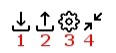
You can also Export your current settings for later use (2). To set up attribute matching, use Edit Matching Attributes (4)
- To create a new definition, you can either click the "+" in the top right of the panel, or extract a definition from an existing file using the Generate option. Whichever method is used, the Name field is editable up to 36 characters in length.
- Add a Description for the definition - this should describe the context in which the definition would be applied. This is the description that will appear in the UG Planning Report alongside the corresponding activities to which the definition has been used to create.
- Set the values for your previously-defined matching attributes. The combination of values for all columns under Match By must be unique for each definition.
- Define whether the current outline entity design string represents the Bottom, Center or Top of the volume to be created, using the Position drop-down list. In other words, this selection denotes the position where the original outline will sit after projection; that is, whether to project above, below, or half above and half below the current plane.
- Your outline shape can be created by a vertical or horizontal projection from the design string. This is determined using the Direction drop-down list.
- Enter an extrusion Distance, This determines how far a shape is extruded upwards, downwards or both from the outline design string.
- Segmenting specifies how
a particular outline is broken up into mining segments. The units
used are as specified in the Studio
UG Project Settings screen.
- [None]: this default option
will segment the design string at every vertex. This is useful if
variable length segments/activities need to be defined.
If you set <None> as the segmenting method, and you don't define an Azimuth direction, it will not be possible to calculate Length. If an Azimuth is defined in this case, the Length is calculated automatically based on the Azimuth value for all outlines of the target design definition. - [By Number]: specifying a number greater than zero will result in segments which are that size. End segments of a string are combined to the previous segment if they are less than 50% of the specified length. Zero is not permitted. With this method, the Number field must contain a positive value greater than zero.
- [By Length]: enter the length
of each segment to create equidistant segments along the string. End
segments of a string are combined to the previous segment if they
are less than 50% of the specified length. With this method, the Length field must contain a positive value greater than zero.
The smaller the segment length, the greater the level of detail that can be reported. Reducing the segment length increases the number of records in a project; it is therefore necessary to find a compromise between acceptable data resolution and project size.
- [None]: this default option
will segment the design string at every vertex. This is useful if
variable length segments/activities need to be defined.
- If your Segmenting Method (see above) is either By Number or By Length, you need to set up Orientation
settings. These settings determine how data will be segmented into activity solids, using the context menu provided in the Orientation table column. The first choice is the Method:
- A calculated Centreline thoughout the outline polygon. This is an automatically calculated centreline that will attempt to mimic the direction of mining from the start point of the activity to the end. Outline shapes are varied, and in cases where a centreline is easily implied, this is generally the most suitable option. With this method, the azimuth of the subdivided block walls can either be orthogonal to the centreline (and potentially variable), fixed to a particular azimuth or read from the OUT design string file. This method may be suitable for outline shapes where a centreline is obvious, e.g. without severe kinks or pinch points which may make a centreline calculation ambiguous.
- A Bounding Box. This method works by rotating a given outline by the segmenting azimuth, and then taking the axis aligned bounding box's extents in the Y direction to produce a reference line that must extend across the entire outline, the reference line is then rotated back to the original system. We then have a reference line that extends exactly across the entire outline at the given azimuth (like map callipers). The segmenting then proceeds in a similar manner to the [Centreline] method using that reference line.
Both methods require a Direction to be specified: - Calculated will generate a centreline that attempts to adhere to the Azimuth value (see below). It will reverse the calculated centreline, if required to get closer to the preferred direction.
- Defined Azimuth will either create a straight centreline at the specified Azimuth passing though the centre of the outline, or use a bounding box with the Y axis aligned in the same manner.
- Dynamic Azimuth is useful if your OUT design string field contains a numeric column representing azimuth values. Selecting this field would then force the orientation of the centreline or bounding box (depending on the chosen Method) to align to the location-specific values. If this option is selected, the Azimuth Field Name field becomes available.
- If the Bounding Box method is chosen, you also need to specify how the bounding box will be oriented throughout the outline polygon, choosing from either:
- Horizontal, the default setting, meaning reference lines for bounding box orientation are horizontal, and so the segmenting distances will also be horizontal.
- Wireframe produces oriented bounding box shapes as projected to the surface that would result by wireframing the outline. So the segmenting distances by default, are taken along the "slope" of the outline. If selected, you will need to select a Wireframe to act as a control surface.
Note that Studio UG does not support segmenting that results in multiple parts (think trouser legs). So in cases where a segmenting bisection involves more than two crossings over the outline, it will be rejected and reported as an error - this in itself should also be tested.
Here's some outline design file segmentation examples
- Set up your Minimum Width.
This is the minimum permissible mining width and is an important setting
to ensure generated solids are practically mineable with existing
equipment.
If some or all of the volume created by projecting the design outline falls below the Minimum Width value, ti is expanded so that the whole design complies with that width, e.g.: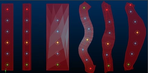
(Transparent solids shown over original outline design strings, plus corresponding activity points) - Select your default value set from the Default Values column. This will contain, for example, the default DENSITY value for the selected design item.
- Under the Default Constraint
column you can choose whether to mine a particular fixed cross sectional
type;
These are the scheduling constraints that will be applied to each activity for scheduling in . These are default values. If scheduling constraints have been imported then these take precedence- As soon as possible
- As late as possible
- Specify a Default Rate (say, 20 m/month or 1m/day) for each fixed cross sectional type. These are default values. If scheduling constraints have been imported then these take precedence over these default values.
-
Choose a Default Dependency Method. By default, activities will Start after latest predecessor, meaning they will continue from the most recently available (and appropriate) activity. You can choose Start after earliest predecessor instead, meaning the activity will start as soon as the first activity link reaches it.
Note: Default dependency method values can, depending on your transfer options, be exported to an schedule, and will be reflected in any dependency animations you run. See Transfer Data to DTS and Animate a DTS Schedule.
- The Exclude column is used to define sections of the design which will be excluded from the connection. This can be useful if there are construction lines within the design or when sections of the design have been mined.
-
Once all entities (that you wish to use in your project) have been fully defined, you can apply them to your project's design strings.
Click OK to dismiss the Design Definitions panel and return to the Apply Design Definitions panel.
- The list of all defined, imported and/or generated definitions appears under the OUT tab (shown by default).
-
To apply your definition(s) to your design data, you first need to load the corresponding design type data into memory; click Load Designs. This will load all data that has been defined in Project Settings as OUT type.
Note: If you need to edit your design data in Project Settings, you will need to Unload any data before you can leave the Apply Design Definitions panel. If data is already loaded, this option will not be available and design strings will already be visible in the 3D window.
-
Once you have applied all definitions to all required string entities, click Save Designs to update the Studio UG database.
-
Click Unload Designs to unload the current data set and move onto the next task.
Related topics and activities