|
|
Studio UG Tutorial - Design Files Defining your input design data |
Underground Planning Tutorial - Design Files
The design data that is used for this tutorial comprises four string files and one wireframe file pair (points and triangles).
These files are:
-
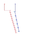
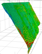
fxs_decline.dm:
A string file generated by Studio's optimize-decline command, representing a loopback decline drive and sole access to the levels. This will form the basis for a fixed-cross sectional solid. -
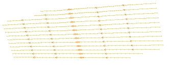
fxs_levels.dm:
A string file comprising multiple string entities representing per-level access drives to the stopes. This will form the basis for fixed-cross sectional solids. -
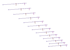
fxs_oredev.dm:
A file containing ore development strings. This will form the basis for fixed-cross sectional solids. -
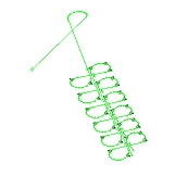
fxs_vent.dm:
A string file representing two vent shafts. This will form the basis for fixed-cross sectional solids. -
stopes_tr.dm:

Wireframes representing mineable stopes, as generated by Datamine's Mineable Shape Optimizer tool. Individual stopes are delineated by the STOPE field value. This data will be an "Imported Wireframe" design type. -
bm_benching.dm:
The model file that will be evaluated and depleted according to the interrogation rules defined below.
The following exercises set these files as your design data for the upcoming planning project.
Prerequisites
-
You have created a new tutorial project as described in the previous section (Project Setup)
-
You have downloaded tutorial data and installed it as described in the previous section (Project Setup)
Exercises in this section
This section contains the following exercises:
Exercise 1: Design Files Setup
The following exercise installs the 5 design files into your planning project. Four will ultimately become the guidelines for fixed cross-sectional solid creation and one (the wireframe) will be segmented to form inter-wireframe activities.
- The Settings panel should be displayed. If not, activate the Planning ribbon and click Settings (or Show, then Settings if it is not initially enabled).
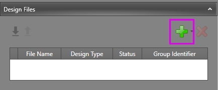
- Initially, there are no design files associated
with your project. To add one, click the green "+" button
in the Design Files group:
- You're going to set up the decline string as a fixed cross-sectional design type. From the menu provided, select [Fixed Cross Sectional] to display the Project Browser.
- In the Project Browser, Files section, select "fxs_decline.dm" (you could also use the browse button to select it from disk).
- With fxs_decline
selected, click OK. A
new item is added to the Design
Files table:
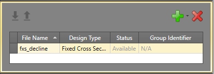
The Status: 'Available' means the file can be found on disk where is expected (Status can be useful if the file is accidentally moved or renamed later on).
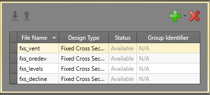
The Group Identifier field is used to denote if and how the file should be subdivided into sub-data; this setting is only relevant for Wireframe design types, so is unavailable here. - Add the files "fxs_levels.dm", "fxs_oredev.dm"
and "fxs_vent.dm" to the table, also using the [Fixed
Cross Sectional] (FXS) design type and the same default settings.
Your table now looks like this:
- The final file "stopes_tr" is a wireframe. This needs to be added using the [Wireframes] design type. Browse for the file "STOPES_TR.dm" and Open it. Click OK to add this fifth entry to the design files table.
- Unlike the FXS design data, the wireframe needs
to be scheduled according to the independent stope shapes held
within it. This information is determined by the STOPE
field in the wireframe's triangle file. This is also referred
to as the wireframe's Group
Identifier.
A Group Identifier is mandatory when defining wireframe design data. As soon as you add the wireframe to the Design Files table, a warning is issued: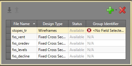
- The stopes_tr file needs to be scheduled on a stope-by-stope basis, so expand the Group Identifier field and select the [STOPE] attribute. This denotes independent stopes within the wireframe file.
- All five design files for your tutorial project are now set up.
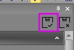
- Save your changes using the Save
button in the top right of the panel:
The next step is to define how your schedule activities will be named. This is described in the following exercise.
