
Insert Variogram Fans
Variogram fans can be inserted under any assay or domain type in your project. Variogram fans can also be inserted under a Data Loader Component, but an assay must be selected.
There are three levels of variogram fans that must be inserted below each other in the Project Tree. These are the horizontal fan, across-strike fan and dip-plane fan. For more information on selecting the maximum continuity direction, see Selecting the Direction of Maximum Continuity on Variogram Fans.
Activity Steps
- Right-click on the relevant component in the Project Tree and select Add » Horizontal Continuity Fan from the menu.
The horizontal continuity variogram fan displays with a green background.
- Modify any settings required in the Property Panel.
-
In the Update tab, click Update.
Contours display on the variogram fan.
Note: If no contours display, check the Standardise gamma values option in the Fan tab of the Property Panel.
- Select the continuity direction by clicking and dragging the protractor (pink arrow).
The angle chosen displays next to the name of the variogram fan in the Project Tree.
- Right-click the horizontal fan you inserted in the Project Tree and select Add » Across Strike Continuity Fan from the menu.
The across strike continuity fan displays.
- Select the continuity direction as above.
- Right-click the across strike fan you inserted in the Project Tree and select Add » Dip Plane Continuity Fan from the menu.
The dip plane continuity fan displays.
- Select the continuity direction as above.
When all variogram fans have been inserted, the Project Tree should look similar to the image below.
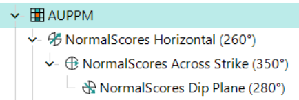
Note: You can go back and edit any of your variogram fans throughout your analysis. If the variogram components in the Project Tree display in bold and their backgrounds are green in the Main Canvas when selected, then you need to update them to see the updated results.