Local Settings
The Local Settings screen has many settings to customise how DataBlast Pro displays holes and patterns by default in the Viewport. These local settings also include some caching and timout settings.
These settings are specific to each DataBlast Pro user.
Standard Hole and Primer Display Factors
- Hole Diameter Scale Factor—A multiple of the hole diameter to determine the size of the collar icon displayed on the Viewport.
- Hole Diameter Scale Factor - Depth Reports—A multiple of the hole diameter to determine the size of the depth variation cylinder displayed in the 2D/3D depth reports in the Drill and Measure modules.
- Hole Text Scale Factor—A multiple of the hole diameter to determine the size of the text (for example, the hole ID) displayed on the Viewport next to each hole.
- Use Fixed Hole Text Size—Whether to display hole text based on a fixed size rather than a multiple of the hole diameter.
- Hole Collar Flag Scale Factor—A multiple of the hole diameter to determine the size of the collar flag if it is shown.
- Hole Primer Scale Factor—A multiple of the hole diameter to determine the size of the primer display on the charge holes in the Charge module.
- Hole Strata Intersect Scale Factor—A multiple of the hole diameter to determine the size of the strata intersection display in the Charge module.
Firing Simulation Scale Factors
- Surface Fired Scale Factor—A multiple of the hole diameter to determine the default size of the non-electric surface detonator firing display. Maximum: 100.
- Hole Fired Scale Factor—A multiple of the hole diameter to determine the default size of the firing display when hole tracks are off. Maximum: 100.
- Primer Fired Scale Factor—A multiple of the hole diameter to determine the default size of the primer firing display when hole tracks are on. Maximum: 100.
- Deck Fired Line Width—A multiple of the hole diameter to determine the default fired display when running the Hole Track Expanded simulation. Maximum: 17.
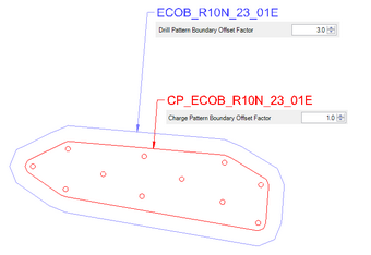
Pattern Boundary Offset Factors and Label Size
Set each of these offsets to slightly different numbers so that the pattern boundaries are offset from each other when displayed in the Viewport.
Hole Collar Item Scale Factors
- Wet/Dewatered Collar Factor—A multiple of the hole diameter to determine the size of the wet/dewatered hole collar display.
- Reactive Collar Factor—A multiple of the hole diameter to determine the size of the reactive hole collar display.
Tree View and Property Grid Settings
- Tree View Item Checked Colour—The colour of items in the DataBlast Items Tree when they are checked on or loaded.
- Tree View Item Active Object Colour—The colour of items in the DataBlast Items Tree when they are checked on and are the active item.
- Tree View Item Select Object Colour
- Tree View Item Hidden/Deleted Text Colour—The colour of text for deleted or hidden items in the DataBlast Items Tree.
- Property Grid Maximum Objects Per Node—The maximum number of objects that are summarised in the Properties Pane. For example if set to 500, when more than 500 holes or other CAD items are selected on the screen, the Properties Pane does not provide summary data. This setting is used to limit the potential of retrieving too much data from the database in one go.
- Show Hidden/Deleted Items in Tree View—Whether to show or hide deleted items in the DataBlast Items Tree.
Initiation Factors and Settings
- Initiation Point Scale Factor—A multiple of the hole diameter to determine the size of the initiation point tag displayed in the Initiation module.
- Truck Lines Line Width—The size of the line representing non-electric surface detonator links. Maximum: 17.
- Trunk Line Arrow Scale Factor—A multiple of the hole diameter to determine the size of directional arrows displayed on non-electric surface detonator links.
- Electronic Relief Segment Scale Factor—The size of the relief segment tag displayed in an electronic timing design.
- Default Wire-Up Search Distance—The default search distance width for automatically linking segments, such as in the Add Trunk Link Auto tool in non-electric timing designs.
- Hole Detonation Period—When reviewing the Firing Simulation analysis and using the Hole Track Expanded playback style, the charge column detonation for each deck is simulated in the playback. The Hole Detonation Period sets the default duration of the charge column detonation before going grey.
- Deck and Explosives per Delay Window—The default value used to determine the timing window for initiation analysis such as Maximum Instantaneous Charge and Decks Per Delay.
- Initiation Contour Interval—The default value used to determine the contour spacing for Initiation Contour analysis.
- Contour Lines Line Width—The default display width for the contour lines in the Initiation Contour analysis.
- Allow Auto Tie Direction Change—Whether to force 'single path' non-electric ties to be in the correct direction from the initiation point.
- Allow Calculation of Partial Blast—Whether to allow analysis of incomplete non-electric blast designs.
- Delay and Vibration Timing Window—The value used to determine the timing window for Initiation Vibration analysis.
- Initiation Vibration Weighted Scaling Factor C
Drill Log Fault Records Settings
- Drill Log Import Fault Records Retrieval Max—May be set to cut off import of poor quality drill logs.
CAD Settings
- Mouse Wheel Zoom—The direction of zoom with the mouse wheel. Select from In and Out.
- Default Font Text Height—The default text height.
- SHX Font to Use on Document—The font to use in screen labels Select from bigfont for bold and txt1 for fine.
- Hole Accuracy Radar Hole Diameter—The search radius for validation of imported drill data.
- Drawing Background Colour—The background colour of the Viewport.
- Drawing Background Gradient—Whether to display a background gradient colour in the Viewport.
- Drawing Background Colour Gradient—The background gradient colour of the Viewport.
- Drawing Background Colour Gradient Angle—The direction of the background gradient.
- Print or Print to PDF Closes Printing—Whether to close the print options after printing or printing to PDF.
- Default to PDF for CAD Printing—Whether to print to PDF instead of to a network printer.
- Display Cursor Circle Radius—The size of the fixed circle cursor guide in the Viewport.
Charge Standard Apply
- Charge Standard Apply Timeout—The timeout value for an unresponsive charge standard.
Database and Cache Settings
- Database Transaction Timeout—The timeout value for an unresponsive database.
- Database Deadlock Retry Count—The number of query retries if there is a database deadlock.
- Use Snapshots
- Hole Pattern Minimum Cache Time
- Charge Standard Minimum Cache Time
- Surface Minimum Cache Time
- Mine Block Minimum Cache Time
- Logging Level—The level of DataBlast Pro application logging that provides details for troubleshooting.
- Number of Logs to Keep—The number of logs to keep in the logs directory before the oldest is deleted. Each log represents one day.
Drawing/Rotation Settings
- Scene Rotation Speed—The speed of the 3D rotation tool in the Viewport.
- Lock Z Axis Rotation by Default—Whether to lock the Z axis by default when rotating 3D drawings. The View Toolbar includes an option to lock or unlock the Z axis rotation as required.
- Scene Rotation Props—Select from None and TopRestrict. If set to TopRestrict, drawings cannot be rotated below the XY plane; that is, drawings cannot be rotated upside down.
- Line Draw Quality Mode
- Dynamic Rotation Flag
- Show CAD View Cube by Default—Whether to display the compass cube by default in the Viewport. The Grid and Snap Toolbar includes an option to show or hide the compass cube as required.
- Show CAD UCS Axis by Default—Whether to display the user coordinate system indicator by default in the Viewport. The Grid and Snap toolbar includes an option to show or hide the user coordinate system indicator as required.
- OpenGL Double Buffered