
Section Viewer Tool Bar
The tool bar gives you access to all the essential actions related to the Section Viewer.
Note: By pressing H, you can show/hide the help for the different keyboard shortcuts available.
-
 Click Attach / Detach from Workspace to attach / detach the 3D view to / from the global interface of Isatis.neo.
-
 Click Save Scene to save modifications in the current scene.
-
 Click Save Scene as to save modifications in a new scene.
-
 Click Save scene in batch to record in batch the content of the current Section scene. The different items, as well as their properties and the camera position are saved but the decorations (compass, gnomon, background color, etc, depend on the Setting up Preferences). This functionality is only available if a batch file is being recorded.
-
 Pick a borehole using the Pick Mode (the selected object can be a top, a label, a sample or a contact) and click Display Logs to display the values of a variable along the selected borehole in a dedicated Display Logs window.
-
 Click View Mode (or use the keyboard shortcut Escape to switch between view and pick mode) to be able to move (left mouse button), zoom in, zoom out (mouse wheel) the view.
-
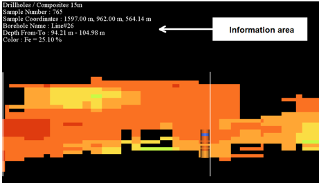
 Click Pick Mode (or use the keyboard shortcut Escape to switch between view and pick mode) to get information on any object (displayed in the upper left corner of the Display Window and in the Messages window) by picking it in the Display Window.
-
 Click Seek Mode (or use the keyboard shortcut K) to set the viewer in "waiting-to-seek" mode. When clicking on a point in the view, the camera will be repositioned so that the camera focal point lies on the point of the geometry under the mouse cursor.
-
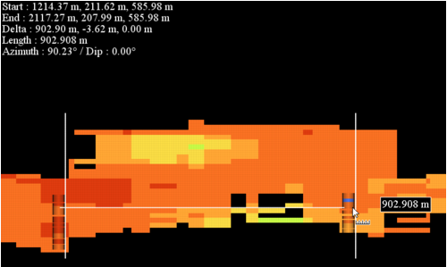
 Click Ruler and pick two objects of the scene (boreholes, results or surfaces) to measure the distance between them. The 3D length of the drawn line is displayed in a label box.
The following information is available in the 3D view when using the 3D ruler: Start point coordinates, End point coordinates, as well as the DX, DY, DZ, 3D length, Azimuth and Dip of the drawn line.
Press Shift-key while moving the mouse to pick the end point to constrain the ruler to the closest principal axis (X, Y or Z).
-
 Click View all (or use the keyboard shortcut Home) to change the camera position in order to visualize all objects.
-
 Click Show axes to display or hide the graphic axes and the corresponding valuations.
When displaying a fence:
- Horizontal axes represent the distance in the XoY plane relative to the first picked point of the fence path (this first point corresponds to 0).
- Vertical axes correspond to the depth of the fence. If the fence is vertical, it corresponds to the Z elevation (i.e you will have the same values as on the 3D scene).
When displaying a clipping plane:
- Horizontal and vertical axes represent the distance relative to the clip plane manipulator location.
-
 Click Show axes grid to enable or disable the background grid in the section view. This functionality is only available when the Show axes tool has been activated.
-
 Select/deselect Show gnomon to display or hide the gnomon. This option is only available when displaying a clipping plane (i.e. it is not available for fences). When the section is aligned with the coordinate system, it shows the system axes. In the other cases, the orientation is given using the geologist convention.
-
 Click Invert colors to modify the background color (black or white) of the display window.
-
 Click Show fence path to display the fence pillars (i.e. the picked points which form the fence panels) and their corresponding length as labels. This functionality is only available when displaying fences (i.e. it is not available with a clipping plane).
-
 Click Fullscreen to enlarge the view to the entire screen.
-
 Click Send to Report to copy the current view in the Reporting window.
-
 Click Copy to Clipboard to copy the current graphic in the clipboard. The clipboard may then easily be pasted to other applications (Word, PowerPoint, etc.).
-
 Click Save as Image to save the current view of the scene in an image file. By default, images are saved as *.png.
Define the Scene you want to save. By default the current scene is selected.
Choose the Image ratio and the Image size (S, M, L) of the exported image. The final size in pixels is indicated (800 x 800 pixels by default). Click on Full size preview to see the final size of the image. As the image loading can be heavy when changing these two parameters, the image is greyed out and an Update button enables you see the final result once you fixed the ratio and the size.
-
Click on
 to define the File name in which the graphics will be stored. By default, they will be put in the public folder of the project and will have the same name as the scene. Click on
  to retrieve the default path and file name.
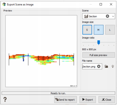
- Z Scale: The vertical scale may be modified to enhance or flatten the relief effect. A list of scale factors is provided. Click on
 Set to Preferences to define the selected Z scale as the default value (visible in the 3D Views section of the Setting up Preferences). If you modify the Z scale, click on to get the default value back.