
Configure Stope Quadrilaterals
Stope Quadrilateralsis one type of Advanced Slice Frameworks.
The Stope Quadrilaterals framework lets you define custom 4-point stope tubes by specifying both top and bottom horizontal extents.
This method allows asymmetric tube shapes and is ideal when your deposit geometry requires non-parallel walls, angled faces, or non-uniform cross-sections. It is an extension of the trapezoid concept, allowing more geometric complexity and flexibility, useful for structured deposits or highly optimized mechanized layouts.
With this framework type, the configuration grid expands to define two sets of horizontal extents (U1 and U2), one for the top and one for the bottom, and vertical bounds (V1 and V2).
Some examples of when this framework type may be useful:
-
For maximum 2D control in stope geometry without jumping to full polygon models.
-
In structured tabular deposits requiring precise bounding on both ends.
-
Where clean rectangular or slanted geometries must be honored.
-
Useful in mechanized stoping, room-and-pillar layouts, or layered stope panels.
Activity steps
-
Display the Framework screen.
-
Expand Framework Type to select Advanced Framework, if not already selected.
-
Expand Advanced Type and select Stope Quadrilaterals.
-
Enter Min U1 and Max U1 values – The top-left and top-right horizontal extents of the stope (upper base).
-
Enter Min U2 and Max U2 values – The bottom-left and bottom-right horizontal extents (lower base).
-
Enter Min V1 and Max V1 values – The vertical bounds of the top of the stope.
-
Enter Min V2 and Max V2 values – The vertical bounds of the bottom of the stope.
Note: The four value sets above form a four-sided polygon (quadrilateral) in cross-section, meaning you have control over each corner of the stope profile.
-
Enter the Position, that is, the sequence index for stope elements (this controls the order of activities).
-
Save your settings.
Example
Consider the following configuration (click to expand):
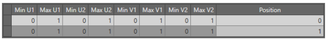
Row 1 defines a quadrilateral:
-
Top – U from 0–1, V from 0–1
-
Bottom – U from 0–1, V from 0–1
Note: This is effectively a rectangle, but the framework allows deviation from this if needed.
Row 2 repeats the same shape, stacked at a different position.
If you adjust U1 and U2 differently, you’ll define asymmetrical tubes or diverging or converging shapes.
Related topics and activities