
Dilution in Slice Frameworks
In underground stope design, dilution refers to the extraction of material that lies outside the economic ore zone. This material adds tonnage without adding value and can significantly reduce the overall profitability of a stope.
In the Slice framework, the annealed stope shape includes planned dilution which is the waste material necessary to extract the ore. Unplanned dilution is material that originates outside the stope boundaries. To factor in unplanned dilution that originates from outside the stope boundaries from the HW/FW or Near/Far a dilution ELOS/Skin can be specified.
An option is provided to evaluate if dilution will make the stope shape uneconomic, and only consider shapes that are economic with dilution. The default mode is to optimize the undiluted shape and then add dilution, but with this control a smaller undiluted shape will be produced and the dilution will include more above cutoff material.
This tab allows you to define the amount, type, and position of dilution around stope shapes, using various estimation methods. The goal is to ensure that the optimization not only targets grade and geometry but also respects expected operational losses or inclusions.
In Slice optimisation, dilution is controlled by where stopes are tested and how they grow, rather than by reshaping stope geometry.
Note: Whilst the principle of dilution are the same for all frameworks, the Prism framework has its own Dilution screen. See Dilution in Prism Frameworks.
Dilution Methods
There are two dilution frameworks supported in MSO:
-
Equivalent Linear Overbreak Slough (ELOS) models dilution as a linear extension around the stope, typically used in narrow vein operations or where geometric overbreak is expected due to blasting.
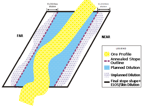
Impact of ELOS dilution on the final stope shape
-
Volume Overbreak Slough (VOS) models dilution as volumes surrounding the stope, offering more flexibility for defining asymmetric or staged dilution—useful for bulk mining.
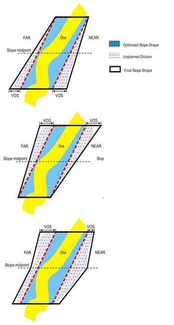
Impact of VOS dilution on the final stope shape
Method Comparison
Below a brief comparison of ELOS and VOS methods for reference.
Note: You can find out even more about these methods in the MSO Reference Manual.
| Category | ELOS | VOS |
| Dilution Concept | Models linear overbreak along stope walls (like a skin or slough layer) | Adds block-based volumetric dilution cells outside the stope geometry |
| Use Case | Narrow vein mining, shrink stoping, small-scale operations | Bulk stoping, sublevel stoping, large-scale operations |
| Application Types |
|
|
| Dilution Sources |
|
|
| Supported Zones |
|
|
| Curve Table Support | Yes (with Dilution At Type options) | Not supported |
| Dilution At Type (Curve Table only) |
|
Not applicable |
| Per-Zone Control | Individual control of hangingwall and footwall | Individual control per zone and direction (Near/Far) |
| Typical Control | Simple – set dilution by geometry or curve | Detailed – assign dilution per direction and zone, with full model field flexibility |
Summary
This part of the MSO workflow is used to:
-
Add overbreak (ELOS/VOS), smoothing, annealing, merging, splitting, and more.