
Intersect Drillholes with Wireframes
To access this command:
-
Using the command line, enter "intersect-drillholes-wireframes"
-
Use the quick key combination "idw".
-
Display the Find Command screen, locate intersect-drillholes-wireframes and click Run.
Use the Intersect Drillholes with Wireframes screen to calculate the points at which selected drillholes intersect specific wireframe data, and write those intersections as a new data points, along with a series of optional attributes, including wireframe thickness values.
Use this command for:
-
Drillhole planning - for example, to ensure that there is adequate coverage of the target (define by an existing wireframe(s)).
-
Safety - to determine where existing or planned drillholes intersect underground excavations ( possibly compromising ventilation).
Intersection points of selected wireframe and all loaded drillholes are created if no drillhole data is previously selected.
Note: You can select data whilst the Intersect Drillholes with Wireframes screen is displayed.
About Thickness calculations
Thickness is the distance inside a wireframe from one side to the other. In some cases this may be measured within a closed wireframe, but in others multiple DTMs may represent the interfaces between different volumes. Note that sense of what is inside a wireframe is determined by the direction of the triangle the point is on. For properly verified objects, this should always underneath true DTMs, and inside of fully-closed wireframes.
Vertical Thickness
This is measured directly upwards or downwards (whatever points inside the wireframe), until it hits another triangle from this wireframe, or another on the list. If no other wireframe is hit in this direction, an Absent thickness is recorded.
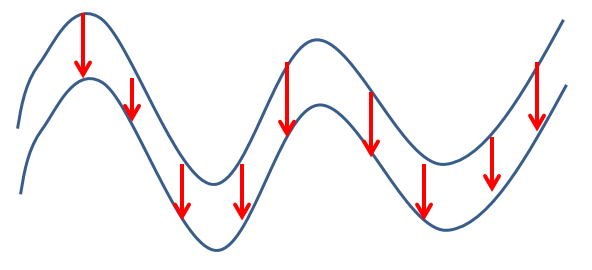
Vertical Thickness of a Seam in Section
View
Horizontal Thickness
This is measured in a direction perpendicular to the triangle, but forced to be horizontal. This distance is measured in this direction until it hits another triangle from this wireframe, or another on the list. If no other wireframe is hit in this direction, an Absent thickness is recorded. For vertical triangles, Horizontal Thickness and True Thickness is the same.
True Thickness
This is measured perpendicularly to the triangle in 3D space, until it hits another triangle from this wireframe, or another on the list. If no other wireframe is hit in this direction, an Absent thickness is recorded. For horizontal triangles, True Thickness and Vertical Thickness is the same.
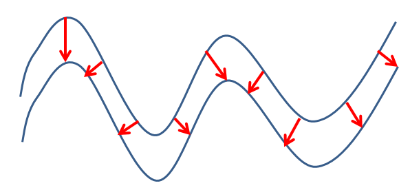
True Thickness of a Seam in Section View
Create Intercept Data
To create drillhole and wireframe intersection points of loaded data:
-
Load drillhole and wireframe data.
-
Display the Intersect Drillholes with Wireframes screen.
-
Choose how data is Output:
-
Select Current Object to have the new points added to the current Points object (if there is one, otherwise this option is unavailable)
-
Select New Object to output the points to a new object with the names defined in the adjacent edit box.
-
-
Choose the wireframe Objects from which to calculate intersection points. Intersection points are created in relation to all loaded drillhole data.
Tip: To create intersection data for a subset of drillholes, filter that data first.
-
Set your command Options. Points can be generated for where a drillhole enters a wireframe or exits a wireframe, or both:
-
Output entry points – Create an intersection point or points (where multiple intercept points occur) where the drillhole first intercepts wireframe data (in the collar to end-of-hole direction).
-
Ouput exit points – As above, but create point data where the drillhole exits wireframe data.
Note: A drillhole is deemed to be entering a wireframe when it has gone from outside the wireframe to the inside, as determined by the triangle orientation set with a tool like wireframe-verify. Drillholes intersecting a DTM will be normally be regarded as entering is when passing from above to below.
-
-
Choose how (or if) you want to Write Attributes to the generated point data:
- Copy wireframe data – Copy all the wireframe attributes from the intersected triangle to the associated point created.
-
Copy BHID – Copy the drillhole BHID column to the associated intersection point.
-
Wireframe name – Copy the object name of the wireframe into the user-defined column in the created point (defaults to WRFM)
-
Intersect # – Add the intersection number of the drillhole and the wireframe to the user-defined column in the created point (defaults to INTSCT). Intersection numbers start at 1 for each drillhole and increment for each intersection for the collar to the end-of-hole.
-
Drillhole Depth – Add the downhole depth of the intersection to the user-defined column in the created point (defaults to DEPTH)
-
Enter/Exit flag – Set the user-defined column (defaults to ENTER) to 1 if the drillhole is entering the wireframe, or 0 if its exiting it.
-
True Thickness – Calculate the true thickness of the wireframe at the point of the intersection, and write it to the user-define column in the created point (defaults to TRUTHICK)
-
Vertical Thickness: will calculate the vertical thickness of the wireframe at the point of the intersection, and write it to the user-define column in the created point (defaults to VERTTHICK)
-
Horizontal Thickness – Calculate the horizontal thickness of the wireframe at the point of the intersection, and write it to the user-define column in the created point (defaults to HORTHICK)
See "About Thickness Calculations, above".
-
Click OK.
Point data is created at intercept points of wireframes and drillholes.
Related topics and activities