
Point Reconstruction Console
To access this console:
-
Activate the Surfaces ribbon and select Create >> From Points.
-
Enter "wireframe-create-from-points" into the Command Line.
The Point Reconstruction Consolemanages scenarios for point reconstruction. It accesses either the PTCLD2WF process or other proprietary functionality to generate surface or volume data from input points. Various surfacing methods are available. The information below will help you decide on the most appropriate method for your input data.
Before you start, it is recommended that you review the following information: Point Reconstruction Methods and Tips
Define a scenario, reconstruction method and settings (which vary depending on the method you choose), then output and review your output wireframe file. Parameters specified along the way are stored with your scenario, which itself is saved within your project. You can also export and import settings to transfer known good scenario configurations between different systems.
Multiple panels exist to guide you through each stage of setting up a reconstruction scenario, including:
-
Create Scenario: Set up a new point reconstruction scenario, or load an existing one. You can also delete scenarios here.
-
Define Scenario: Choose the point reconstruction method and which stages of point reconstruction you wish to complete (subsampling, normal calculation, surface generation).
-
Subsample: If you are reducing the size of your input data, choose how to subsample.
-
Calculate Normals: If your surfacing method is interpolative and requires surface normals to be created (such as with the Poisson, SSD or Balanced methods), define how normals are created here.
-
Configure Surfacing: If your chosen surfacing method requires additional surfacing parameters (Watertight and Fast Advance methods, for example, do not), set them up here.
You can see settings made for the active scenario on the left of the console. These update automatically as settings are added or changed. Generally, you can't access a panel unless prerequisite information has been provided. This is typically in a top-bottom order.
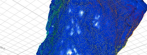
An example of a reconstructed surface based on CMS data
To set up an execute a point reconstruction scenario
The following steps represent the general, high-level approach to reconstructing point data. For more detailed steps for a particular stage, follow the links above.
- Display the Point Reconstruction Console.
- The Create Scenario panel is displayed by defaults. Create, edit or delete a scenario. If required, import or export scenario settings.
-
To choose the scope of your point reconstruction project and surface reconstruction method:
-
Activate the Define Scenario panel. This panel can only be displayed if a scenario has been created previously.
-
Choose your Input point cloud using the Project Browser. This can be any Datamine points file. If the selected file is not yet part of your project, it is added.
General statistics of the selected points file display.
-
-
Choose a surface reconstruction method. See Point Reconstruction Methods and Tips.
Tip: Selecting a method updates the help text and image below.
-
Define the scope of your reconstruction method. Not all options may be available, depending on the surface reconstruction method chosen. See Define Scenario.
-
Subsample your input data, if required.
-
If the chose reconstruction method requires it, Calculate Normals.
-
If your chosen surface reconstruction method requires it, choose your surface reconstruction parameters.
-
Activate the Configure Surfacing panel.
-
Confirm the Point data to be surfaced name and location.
-
-
Calculate your output surface based on existing parameters. This panel is only available if all prerequisite information is available to create a surface for the chosen reconstruction method.
-
Activate the Configure Surfacing.
-
Confirm the Point data to be surfaced name.
-
Confirm the Output surface file name. By default, a wireframe file pair is generated using the input points file name and a "tr.dm(x)" and "pt.dm(x)" suffix. The base file name will be the most recently-generated interim file name (either subsampled or normalized) or, if no intermediate subsampling or normalizing has been specified, the name of the raw input points file.
-
Choose if you wish to Auto load your generated surface data. If your output wireframe is particularly large or dense, the wireframe may take time to render in the primary 3D window.
-
Select Generate Surface File.
Surface data is generated in the current project folder. A progress indicator displays during calculation.
-
Related topics and activities