
ANISOANG Process
To access this process:
- View the Find Command screen, select ANISOANG and click Run.
- Enter "ANISOANG" into the Command Line and press <ENTER>.
See this process in the Command Table.
Process Overview
Note: This is a superprocess and running it may have an effect on other Datamine files in the project.
The processes ESTIMA and COKRIG include a dynamic anisotropy option that allows the rotation angles for the search ellipsoid to be defined individually for each cell in the model so that the search ellipsoid is aligned with the axes of mineralisation. This therefore requires the rotation angles to be interpolated into the model cells which in turn requires a set of angles as the input data file for interpolation.
Note: ANISOANG can work with both rotated and unrotated input data and can handle inputs of any rotation type.
See ANISOANG Workflow.
The ANISOANG process is designed to assist you to create a suitable input data file, and offers two methods for defining the dip and dip direction of the major axis of anisotropy:
- Digitising strings in plan and section.
- Calculating the angles from wireframe triangles.
If sections are used and are oriented in the dip direction then the output POINTS file will contain the true dip of the mineralisation. If sections are not oriented in the dip direction then the output POINTS file will include the apparent dip. The apparent dip should then be interpolated into the model and process APTOTRUE used to convert to the true dip.
Further information and examples are available in the Dynamic Anisotropy User Guide, and a worked example of ANISOANG.
Plan Strings
File PLANSTR contains strings digitised in a horizontal plan which can be used to define the strike, and the true dip direction is then calculated as 90o or 270o from strike. Alternatively the plan strings can represent the true dip direction, but this would not be the usual case. Parameter PLANMODE is used to define what the strings represent. The direction in which the strings are digitised is important. If the azimuth of a string segment, measured from point N to point N+1, is Ao and PLANMODE=1 or 2 then the true dip direction is calculated as A+90o or A+270o from strike. The XYZ coordinates of the mid-point of the string segment will be written to the output POINTS file together with the strike and true dip direction angles.
Section Strings
File SECTSTR contains strings digitised in vertical sections to define the dip. If parameter SECTMODE is set to 2 then the sections are oriented in the dip direction and so the dip will be the true dip of mineralisation and the orientation of the section line will be the true dip direction. Both these angle will be written to the output POINTS file together with the coordinates of the mid-point of the string segment. If SECTMODE is set to 1 then the sections are not oriented in the dip direction and so only the apparent dip can be calculated. In this case the sections must be parallel, so that they all have the same apparent dip direction. The apparent dip angle can then be interpolated into the model and process APTOTRUE used to convert from apparent to true dip. The direction in which the strings are digitised is important as the dip is measured for each string segment from point N to point N+1.
Wireframes
If parameter TRIPTS=1 the dip and dip direction of each triangle in the wireframe is calculated and written to the output POINTS file together with the coordinates of the centre of gravity of the triangle. The calculated angles are assumed to represent the true dip and true dip direction of the mineralisation. Calculating the angles from a wireframe is particularly suitable for narrow seams where the mineralisation follows the hangingwall and / or footwall, but is not so appropriate for massive deposits or narrow veins of irregular shape.
Input from wireframes and digitised strings can be used together. However in this case the string sections must be oriented in the dip direction so that true dip and true dip direction angles are calculated by both methods. All output is written to the single POINTS file.
ZONE Field
ZONE is an optional attribute field (numeric or alphanumeric) in input wireframe triangle file that is used to identify individual solid models, optional attribute field in variogram model or optional attribute field in search parameters. The field is assigned to points in the output POINTS file.
If ZONE values between WIRETR and VMODEL or WIRETR and SRCPARM match then a matching rotation is used for determining the dynamic ANGLE3 field. SREFNUM or VREFNUM is used for identifying a rotation for unmatched data.
Note: When a variogram model or search parameter file is used to determine dynamic ANGLE3, the input ranges do not need to be in ascending order. Any axis convention or length order is accepted.
Attribute Fields
Attribute fields can be used to assign fields from the PLANSTR and SECTSTR files to the POINTS file. The attribute fields can then be used as Zone fields when the angles fields are estimated into the block model. The allows the estimates to be made in a single run of COKRIG or ESTIMA.
A set of up to 5 attribute fields can be defined for each point in the plan and section string files. If attributes are not defined then the orientation of each string segment is calculated and the angles are assigned to the mid-point of each segment and saved to file POINTS. If attributes are defined and the values of each attribute are the same at either end of a segment then the attribute values and angles are assigned to the mid-point of the segment. If one or more attributes do not have the same value at either end of the segment then the segment is split in half and the mid-point of each half segment is assigned the attributes of the nearer of the two segment ends. The half segment mid-points are also assigned the angle values.
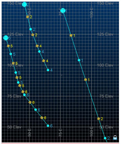
The graphic below illustrates the assignment of attribute fields. Three strings from a SECTSTR file are coloured cyan. Each point in each string is annotated with numeric attribute value A1. Attribute values coloured brown are written to the POINTS file.
Two segments are displayed for the string on the right side of the graphic. The top and bottom of the first segment have A1 values of 1 so the top point will also have an A1 value of 1 (in brown). The second segment has an A1 value of 1 at the top and 2 at the bottom. As the A1 values are different the segment is split into two. The top half segment has an A1 value of 1 at its centre and the bottom half segment has an A1 value of 2 at its centre. The angles and attribute(s) of both points are written to the POINTS file.
The five symbolic fields PLNFLDi, i=1,5, will select attribute fields from the PLANSTR file. They will also select attribute fields with the same field name from the SECTSTR file. Similarly the five symbolic fields SCTFLDi, i=1,5, will select attribute fields from the SECTSTR file. They will also select attribute fields with the same field name from the PLANSTR file. It does not matter if an attribute field is selected twice.
Output Points File
The output POINTS file includes coordinate fields XPT, YPT and ZPT. It also includes a subset of four fields as shown in the table:
|
Field Description |
True
Dip |
True Dip |
Apparent |
Apparent |
|
Field Name |
TRDIPDIR |
TRDIP |
APDIPDIR |
APDIP |
|
Wireframe |
ü |
ü |
û |
û |
|
Plan |
ü |
û |
û |
û |
|
Sections in dip direction |
ü |
ü |
û |
û |
|
Sections not in dip direction |
û |
û |
ü |
ü |
If parameter ADDSYMB=1 then a set of symbol fields are added. These have the reserved field names for displaying 3D symbols in a 3D window.
SYMBOL | Symbol
code. The symbol is selected by parameter PLANSYMB
for points created from plan strings, SECTSYMB for points created
from section strings and WFSYMB for points created from wireframe
triangles. Codes range from 201 to 267 which are shown
in the graphic. |
COLOUR | Colour
of SYMBOL. This is defined by parameters PLANCOL, SECTCOL
and TRICOL. |
DIPDIRN | Field
used to define the dip direction
of the 3D SYMBOL. This is set equal to TRDIPDIR or
APDIPDIR depending on whether true or apparent dips have been
calculated. |
SDIP | Field
used to define the dip
of the 3D SYMBOL. This field is set equal to TRDIP or APDIP depending
on whether true or apparent dips have been calculated. For
plans string data SDIP is set equal to 0 (horizontal). |
SYMSIZE | Size
of the symbol in mm as defined by parameter SYMSIZE. |
| DAANGLE 1/2/3 | Additional fields provided if the ROTATION input is specified. Angles represent rotations around ZXZ. |
If one or more Attribute fields have been defined then the following two fields will be included in the POINTS file:
PT_TYPE Point Type. This defines the source of the Point values:
- PLAN_1 – single segment in PLANSTR file
- PLAN_2 – first half segment in PLANSTR file
- PLAN_3 – second half segment in PLANSTR file
- SECT_1 – single segment in SECTSTR file
- SECT_2 – first half segment in SECTSTR file
- SECT_3 – second half segment in SECTSTR
COLOUR1 Colour field corresponding to PT_TYPE:
- - 2 (PLAN_1), 3 (PLAN_2), 4 (PLAN_3), 5 (SECT_1), 6 (SECT_2), 7 (SECT_3)
Using Search Parameters or a Variogram Model as Inputs
If either a search volume parameters (SRCPARM) or variogram model (VMODEL) input are chosen (if both are selected, SRCPARM is used), an additional field is output - ANGLE3 which may be used in dynamic anisotropic calculations as a rotation around Z-X-Z (3-1-3).
If SRCPARM is specified, search distances must be listed in the input file in ascending order, for example, DIST1 > DIST2 > DIST3).
If a search volume parameter file is specified, it must include a field SREFNUM which defines a unique reference number for each search volume. The SREFNUM parameter then defines which search volume will be used. If the SREFNUM parameter is set to absent data (the default), then the first search volume in the file will be used.
If VMODEL is specified, variogram ranges must be listed in ascending order.
If a variogram model (VMODEL) is specified, then it must include a field VREFNUM which defines a unique reference number for each variogram model. The VMODEL parameter then defines which variogram model will be used. If the VREFNUM parameter is set to absent data (the default), then the first variogram model in the file will be used.
Minimum and Maximum Angles
If angles are derived from a wireframe then it is sometimes useful to specify minimum and maximum values for dip and dip direction. For example if the wireframe represents a seam and is endlinked then the triangles at either end can be eliminated. Similarly the triangles at the start and end of each section could be removed.
@FLAT
The parameter FLAT=1 is set when the calculation of DIP, DIPDIRN and dynamic ANGLE3 from ANISOANG for horizontal or sub-horizontal horizons which may be interpolated into a block model for use with grade estimation using dynamic anisotropy. This aligns local search orientations when the major direction of the variogram or search is predominantly flat (where the major and semi-major (SDIST1 and SDIST2 around SAXIS1 and SAXIS2) are falling in the horizontal or sub-horizontal plane, and the shortest distance SDIST3 is for SAXIS3, is approximately vertical). In this case, ANISOANG will substitute the major direction VANGLE1 or SANGLE1 as TRDIPDIR and vary results of TRDIP and dynamic ANGLE3, calculated from the surface.
Note: Please always validate results using DAELLIPS.
Input Files
Name | I/O Status | Required | Type | Description |
PLANSTR | Input | No | String | Input strings, digitised in plan, defining the direction of the mineralisation. |
SECTSTR | Input | No | String | Input strings, digitised in section, defining the dip and dip direction of the mineralisation. |
WIRETR | Input | No | Wireframe Triangle | Input wireframe triangle file. |
WIREPT | Input | No | Wireframe Points | Input wireframe points file. |
| SRCPARM | Input | No | Search Volume Parameters | Input search volume parameter file adding a dynamic ANGLE3 field when an input wireframe surface is used. Either a SRCPARM or VMODEL should be selected; if both are selected the SRCPARM will be used. This file must contain the fields SREFNUM, SANGLE1, SANGLE2, SANGLE3, SAXIS1, SAXIS2, SAXIS3, SDIST1, SDIST2, and SDIST3, which define the orientation and dimensions of the search volume. Search distances must be in descending order, with SDIST1 >= SDIST2 >= SDIST3. |
| VMODEL | Input | No | Variogram model | Input variogram model file for adding a dynamic ANGLE3 field when an input wireframe surface is used. Either a SRCPARM or VMODEL should be selected; if both are selected only the SRCPARM will be used and the VMODEL will be ignored. This file must contain the fields VREFNUM, VANGLE1, VANGLE2, VANGLE3, VAXIS1, VAXIS2, VAXIS3, ST1, ST1PAR1, ST1PAR2 and ST1PAR3 (for up to 10 structures) which define the orientation and dimensions of the variogram model. Variogram ranges must be in descending order. |
| ROTATION | Input | No | Variogram model or Search Parameter file | Input file (variogram model or search parameter) containing a rotation for aligning input wireframe. Including this option will output an additional three angles [DAANGLE1, DAANGLE2, DAANGLE3] rotated around the axes ZXZ (313) in the output points which may be used for Dynamic Anisotropy with the input search or variogram model rotation. This option will also output a rejected points containing points that fall outside the specifed THRESH1 and THRESH2 |
Output Files
Name | I/O Status | Required | Type | Description |
POINTS | Output | Yes | Points | Output points file including fields SDIP, DIPDIRN, SYMBOL and SYMSIZE. |
Fields
Name | Description | Source | Required | Type | Default |
ZONE | Optional attribute field (numeric or alphanumeric) in input wireframe triangle file used to identify individual solid models, optional attribute field in variogram model or optional attribute field in search parameters. The field is assigned to points in the output POINTS file. If *ZONE between WIRETR and VMODEL or WIRETR and SRCPARM match then matching rotation will be used for determining dynamic ANGLE3 field. SREFNUM or VREFNUM is used for identifying a rotation for unmatched data. | WIRETR | No | Any | Undefined |
PLNFLD1 - 5 | Attribute field in PLANSTR file to be added to POINTS file | PLANSTR | No | Any | Undefined |
SCTFLD1 - 5 | Attribute field in SECTSTR file to be added to POINTS file | SECTSTR | No | Any | Undefined |
Parameters
Name | Description | Required | Default | Range | Values |
TRIPTS | Flag to indicate whether the output points file should include points from triangles. Default 1. 0 = Do not create points from triangles. The wireframe is only used for assigning the ZONE field. 1 = Create points from triangles | No | 1 | 0,1 | 0,1 |
PLANMODE | Flag to indicate how the dip direction is calculated from strings that have been digitised in plan. Default 1. 1 = String represents strike direction, and dip direction is 90 degrees to the direction of strike. 2 = String represents strike direction, and dip direction is 270 degrees to the direction of strike. 3 = String represents the dip direction. | No | 1 | 1,3 | 1,2,3 |
SECTMODE | Flag to indicate whether sections are parallel to the dip direction, thus giving true dips. Default 1. 1 = Sections are not parallel to the dip direction, so apparent dips are calculated. 2 = Sections are parallel to the dip direction, so true dips are calculated. | No | 1 | 1,2 | ,2 |
MINDIP | Minimum value (in degrees) of dip angle to be written to the output points file. If a value less than the minimum is calculated it will be rejected. Default -90. | No | -90 | -90,90 | Undefined |
MAXDIP | Maximum value (in degrees) of dip angle to be written to the output points file. If a value greater than the maximum is calculated it will be rejected. Default +90. | No | 90 | -90,90 | Undefined |
MINDIRN | Minimum value (in degrees) of dip direction angle to be written to the output points file. If a value less than the minimum is calculated it will be rejected. Angles are calculated from minimum to maximum in a clockwise direction. Hence a minimum of 330o and a maximum of 20o will define a window of 50o. If MINDIRN is not defined, or set to absent, it will not be used. If MINDIRN is defined it must lie between 0o and 360o. Both MINDIRN and MAXDIRN must be specified in order for limits to be applied. The default is absent data, so limits will not be applied. | No | Undefined | 0,360 | Undefined |
MAXDIRN | Maximum value (in degrees) of dip direction angle to be written to the output points file. If a value greater than the maximum is calculated it will be rejected. Angles are calculated from minimum to maximum in a clockwise direction. Hence a minimum of 330o and a maximum of 20o will define a window of 50o. If MAXDIRN is not defined, or set to absent, it will not be used. If MAXDIRN is defined it must lie between 0o and 360o. Both MINDIRN and MAXDIRN must be specified in order for limits to be applied. The default is absent data, so limits will not be applied. | No | Undefined | 0,360 | Undefined |
ADDSYMB | Flag to indicate whether symbol fields SYMBOL, COLOUR, DIPDIRN, SDIP and SYMSIZE should be added to the output POINTS file. 0 = Do not add symbol fields to POINTS file. 1 = Add symbol fields to POINTS file. | No | 0 | 0,1 | 0,,1 |
PLANSYMB | Symbol code to select symbol to be displayed for points derived from digitised plans. Valid values are 201-267. Symbols are shown in the Full Description. | No | 216 | 201,276 | Undefined |
SECTSYMB | Symbol code to select symbol to be displayed for points derived from digitised sections. Valid values are 201-267. Symbols are shown in the Full Description. | No | 216 | 201,276 |
|
WFSYMB | Symbol code to select symbol to be displayed for points derived from wireframe triangles. Valid values are 201-267. Symbols are shown in the Full Description. | No | 224 | 201,276 | Undefined |
PLANCOL | Colour assigned to symbol to be displayed for points derived from digitised plans. | No | 1 | 1,64 | Undefined |
SECTCOL | Colour assigned to symbol to be displayed for points derived from digitised sections. | No | 2 | 1,64 | Undefined |
WFCOL | Colour assigned to symbol to be displayed for points derived from wireframe triangles. | No | 3 | 1,64 | Undefined |
SYMSIZE | Symbol size in mm. | No | 2 | 0,50 | Undefined |
| SREFNUM | If a search volume parameter file (SRCPARM) is specified, then it must include a field SREFNUM which defines a unique reference number for each search volume. The SREFNUM parameter then defines which search volume will be used. If the SREFNUM parameter is set to absent data (the default), then the first search volume in the file will be used. | No | 1 | Undefined | Undefined |
| VREFNUM | If a variogram model (VMODEL) is specified, then it must include a field VREFNUM which defines a unique reference number for each variogram model. The VMODEL parameter then defines which variogram model will be used. If the VREFNUM parameter is set to absent data (the default), then the first variogram model in the file will be used. | No | 1 | Undefined | Undefined |
| FLAT | Set to create dynamic anisotropy points for flat lying structure. Using this mode will align points (orientation defined by TRDIPDIR, TRDIP and dynamic ANGLE3 around the axis 3-1-3) with the major direction defined by SANGLE1 (in SRCPARM) or VANGLE1 (in VMODEL). These points are suitable for locally orientating grade estimation with dynamic anisotropy for a horizontal or sub-horizontal surface. Use with WIREPT and WIRETR; and either SRCPARM or VMODEL should be selected. =0 : Create points for a dipping wireframe (Default). =1 : Create points for a horizontal / sub-horizontal wireframe. See "@FLAT", above, for more information. | No | 0 | 0,1 | 0,1 |
Example
!ANISOANG
 &PLANSTR(_VSPLNST),&SECTSTR(_VSSECST),&POINTS(POINTS1),
          @TRIPTS=1.0,@PLANMODE=2.0,@SECTMODE=1.0,@ADDSYMB=1.0,
          @PLANSYMB=216.0,@SECTSYMB=216.0,@WFSYMB=224.0,@PLANCOL=1.0,
          @SECTCOL=2.0,@WFCOL=3.0,@SYMSIZE=3.0,@FLAT=0ANISOANG ... creating
 points from plan strings... creating points from section stringsDip direction
 of section strings (APDIPDIR) = 90Angle creation
 complete - Points file POINTS1 created with 403 records
Related topics and activities
ANISOANG - Worked Example
ANISOANG Workflow
COKRIG Process
ESTIMA Process
Dynamic Anisotropy Overview
Advanced Estimation & Variography - Introduction