|
|
Pit Design Tutorial - Auto Design Automatically generating a pit |

Pit Design Tutorial - Auto Design
This tutorial takes you through some of the basic functions of automated pit design. The concept that underpins Studio OP's Auto Design task is:
-
Benches are projected upwards or downwards and will always honour the following constraints:
-
Face angle
-
Berm (and Catch Berm, if defined) Width
-
Bench definitions
-
Constraint strings, if they lie outside the unmodified pit shell
-
If it is possible to do so, road definitions will be applied, including fixed roads (box cuts and embankments).
-
If it is possible to do so, advanced conditioning, berm tapering and other design modifiers will be applied to the design strings
-
From the generated design strings, a surface is created
-
If required, an evaluation of the overall volume of the phase (the volume created by the designed phase shell and the assigned topography) will be calculated.
In the following exercises, you will create an automated design, including a road. Fixed Road design is covered in a subsequent tutorial.
Prerequisites
-
You have completed Test Ramp Layout.
Exercise: Generate Road Definition using the Phase 1 Shell
In this exercise, you are going to bring together the data created in previous exercises. Studio OP's dynamic pit design process culminates in the Auto Design task and receives input generated (potentially) as detailed here.
- Using the Design ribbon, select Auto Design.
- The Auto Pit Design task is displayed, as are the contour strings generated earlier. If you hadn't already defined everything you need to use the automated design tools, you would be prevented from accessing the task.
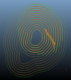
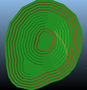
- Zoom-all so you can see all contour strings:
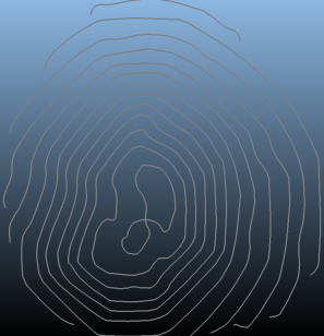
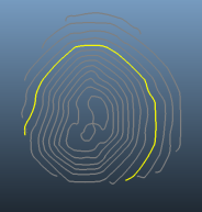
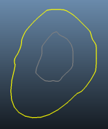
- Select the contour string shown below (left-click).
This will become your pit base string. The lower contours are
not of a suitable area/shape to use as a pit base:
- Click Add selected string(s). This adds the selected string to the pit constraints, meaning that Studio will attempt to honor the shape of the string (providing slope angles and widths allow it) and incorporate some or all of the string shape within the generated pit.
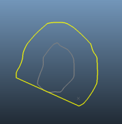
- Disable the Show
Phase Shell Contours and enable the Show
Pit Constraints check box. A single string (the one you
selected previously) should now be displayed.
These are the constraint strings defined so far. In this case, only 1. - Click Recalculate
and a series of pit design strings are generated, with each 'raise'
of the pit being made to correspond with each bench definition.
These preview strings are useful for checking the validity of your road rules (defined in the previous exercise), your slope region information and to see how constraint strings impact the precursor design.
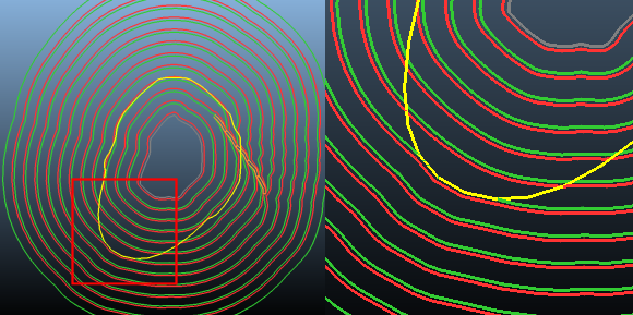
At this stage, if you zoom-all you should be looking at something like this:
- The Auto Design task features a similar set of tools to the Ramp Layout task. This allows you to fine tune your road rules, but this time using the pit design as a canvas. Hide the constraint strings so that only the design strings are shown.
- Click Make
Design Surface to create the pit surface:
Exercise: Editing Contour Strings
In this exercise, you will modify the generated pit design to include contour strings from higher elevations as constraints.
- Disable the view of the design surface,
design strings and pit constraints by disabling the display toggles
at the top of the screen:
- Enable Show Phase Shell Contours.
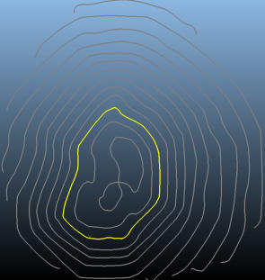
- Select (only) the following contour string:
- Click Add Selected String(s) to add this string to the constraints object.
- Enable the Pit Constraints view (use either the icon at the top of the screen or the Show Pit Constraints check box at the bottom).
- Disable the Show Phase Shell Contours check box.
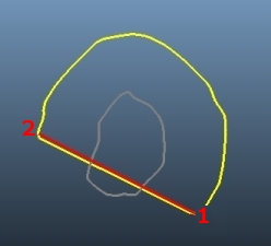
- Contour strings must be closed, so select
the latest constraint string and type 'clo' to close it. The new
edge will span from start - end position:
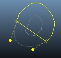
- The insert-curve command is useful for forming a more useful constraint outline. With the constraint string selected as shown above, type 'ics'.
- Digitize a 2-point line as shown below (the
selection order of the points is important:
- The string modifiers will appear - move
them so the new curve segment appears like this:
- Click Done
to complete the command (find out more about insert-curve here).
Note that this modification is not normally required if no additional conditioning is going to be applied during the creation of design strings; normally the start-end string edge that was created will pass harmlessly over the void of the pit shell, but with conditioning the string points are increased and are more likely to be considered when generating the design string at the upper level (in this case). - Click Recalculate
using the toolbar at the top of the screen to see how this impacts
the design strings:
The effect is subtle (or if you haven't created a sufficiently extended loop - may not impact the design at all), but the top edge of the pit has been pushed out slightly to honor (as closely as the design constraints and parameters will allow) the new constraint string. - Make Design
Surface again to update the pit shell.
- Modify the constraint string again (again,
using insert-curve-segment with the same starting points) to further
extend the pit wall, e.g.:
Exercise: Visualization Options
In this exercise, you will see the effect of some of the additional visualization controls that can be used to add more information to your design strings and generated surface.
- Enable the display of the Design Strings. Disable all other visualization options.
- With the Design Strings displayed, re-enable Mark Design Strings Above Topo.
- Recalculate the design
strings - string data above the assigned topography (Surface
Topography task) is now displayed as a dotted line:
- You can also enhance your design strings automatically when
the pit surface is generated, by adding a pit rim string to the
strings data to highlight the intersection of the pit wireframe
and topography.
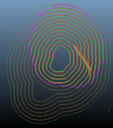
Enable the Add Pit Rim to Design Strings when Making Design Surface check box and click Make Design Surface. - Disable the Show Design Surface
check box to display only the design strings. Note that a pink
pit rim has been added:
- Use the Pit Data control
bar to enable the view of the topography:
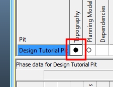
- Double click the filled circle under Topography to display the Wireframe Properties dialog.
- Set the Opacity slider to approximately half way (50%). Click OK.
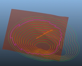
- You can now see how the visual formatting has been applied
both above and below the topography, and that the pit rim neatly
coincides with the intersection of the two surfaces:
- Another option available to you is to include surrounding topography
data with the generated design surface.
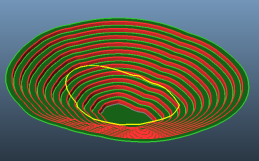
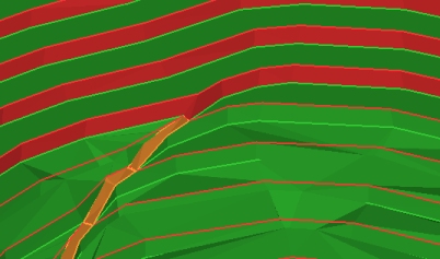
Select Combine Design Surface with Topo and click Make Design Surface- the result is a design surface that incorporates the topography, overlaid with design strings differentiated to show areas above and below the topography.
At this point, you can disable the view of the topography by selecting the filled circle in thePit Datacontrol bar.
The pit rim is also highlighted (note that the pit surface has been colored pink for demonstration purposes only - normal coloration would show green and orange benches/berms):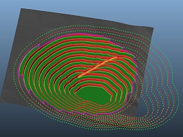
- Finally, move the road end point to meet the topography using
the Move End Elevation
button.
Right-click the point shown below to extend the road, then click Make Design Surface to recreate the pit surface with the new road terminal elevation: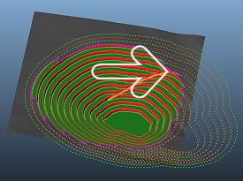
Exercise: Fine-tuning the Pit
In this exercise, you will specify additional parameters to control how the design strings are produced with respect to the constraints. You will apply conditioning to remove points considered for berm string generation, remove strings that fall below a calculated area and
- Select the Conditioning tab at the top of the Auto Pit Design task. This contains parameters that control how (and if) a design string is created.
- In the Minimum
Deviation cell for the "Pit Defaults" row, enter
a value of "5". This performs a 'pre-simplification'
of the data used to create design strings; points that fall within
a straight-line distance of 5m from another point will be removed.
In effect, this setting removes the data that is used to generate
design strings, resulting in a coarser data object.
Using the toolbar at the top, click Recalculate.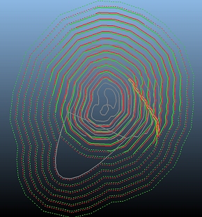
Note how the pit design strings have become more angular due to the reduction in points. - Next, return to the Conditioning
tab and enter an Inside Fillet
Radius of "35" and an Outside
Fillet Radius of "45". This setting applies an
automatic string filleting effect to the design strings, working
in the designated mining direction (in this case, bottom up).
You use these fields to specify the maximum
curvature radius permitted between line segments on a selected
string. Points will be added to the line as required.
Using the toolbar at the top, click Recalculate. The design strings are updated to include the new filleting parameters - you will see that they are less angular than before.
The effect of filleting can be subtle and will depend on the shape of the pit parameters and input data. In the image below, the non-filleted boundary (zoomed in) is shown in purple and blue (crest and toe) whilst the filleted equivalent is shown in dark and light green: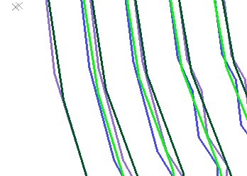
Filleting in this way is a useful way to remove unnecessarily complex string geometry with multiple changes of direction within a small area; this can trigger, for example, rosette influence due to the presence of a wide range of azimuths along a string. - Set the Minimum Deviation back to zero.
- Return to the Auto Pit Design panel and disable Combine Design Surface with Topo, Add Pit Rim to Design Strings When Making Design Surface and Mark Design Strings Above Topo.
- Use the Pit Data control bar to disable the display of the topography.
- Recalculate
the design strings, disable the Combine
Design Surface and Topo check box and Make
Design Surface. Show only the design wireframe and hide
all other objects:
- Zoom in on the road termination point as
shown below:
- You can edit your pit by editing the required string(s), setting it/them as constraints, and regenerating the design surface.
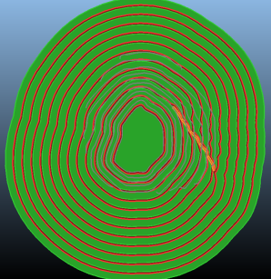
- Hide the design surface and show the design strings, maintaining the view direction and zoom level above.
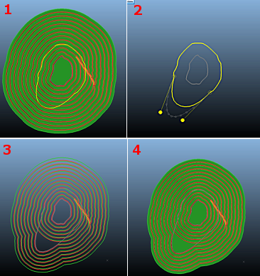
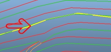
- Edit the highlighted road (yellow) using
the Move Points command
(Edit ribbon) as shown
below. The plan is to edit the crest string immediately above
the road entry point:
Make sure that the toe string you are editing isn't moved to a position where it undermines the surface - it has to be within the boundary of the next design string in the bottom-up direction. - Next, make sure the modified crest string
is selected, click Add Selected
String(s).
This will include the modified pit as a constraint. As the pit was pushed outwards, the existing slope region settings will not be violated (if pushed inward, the string modification would be ignored in the projected pit as the new string nodes would contravene the pit default slope angle requirement).
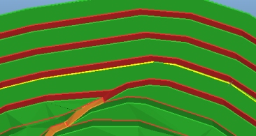
Turn the design strings off and enable the Show Pit Constraints check box. You should now see the three constraint strings that will be used to control the pit surface generation.
Select the constraint strings to highlight them in yellow. - Click Recalculate
to see the position of the new design strings - this time, the
recent pit modification has been included:
From this point onwards, you only need to modify the constraint string and recalculate if you wish to make further modifications to the pit. Adding more constraint strings based on the design strings is as easy as outlined above. Once added, they become a modifiable resource for pit generation. - Click Make
Design Surface to see the new shape:
The modified design now includes a widened bench at the 200m elevation. - Experiment with adding more design strings to the constraints object, modifying them and regenerating your pit.
- Save your project.