
Auto Pit Design

To access this screen:
-
Activate the Design ribbon and select Pit Modelling >> Auto Design. The Auto Pit Design tab is shown by default.
Note: This task is part of Interactive Pit Design functionality.
This screen is a part of the Auto Pit Design task, a collection of panels contains functions for automated open pit design.
For information relating to dump design, click here.
This is the main console for generating pit data from your constraint strings, slope regions, bench definitions, road definitions and pit/phase information. This is where you set up the key parameters for your pit design including selection of constraint strings, interactive road editing (both adaptive and fixed types). Pit generation is initiated using this panel.
Once the Auto Pit Design panel is active, you can also define automated design template sets.
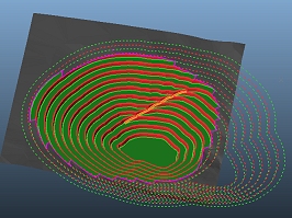
The purpose of interactive pit modelling functions is to enable engineers to rapidly produce and evaluate alternative open pit mine designs based on strategic plans and to refine the designs as mining progresses.
Warning: You cannot use the Auto Pit Design task for pit design if your benches have been defined using imported 3D surfaces. This task requires benches to be defined by elevation and height only.
These designs will adhere to all specified slope region constraints and other general and per-bench constraints the control the blending of road segments and direction change restrictions (Conditioning) and how pit berms adapt in relation to in-pit road networks (Berm Tapering). Finally, you can manage advanced options such as how road design strings are used, which evaluation legend is used for reporting and view formatting in the managed task 3D window.
See Auto Design – Designing Adaptive And Fixed Roads.
Tip: Constraining Surfaces, Adaptive Roads and Fixed Roads command groups can be expanded and collapsed.
Pit Roads
Your pit road network can be designed using either adaptive or fixed roads:
-
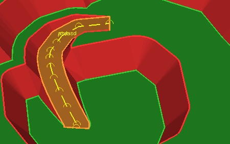
Adaptive roads confirm to the contours of your pit design strings and are ultimately used to modify the pit wireframe surface to embed the road in a realistic manner. Adaptive roads always start on one pit design string and end on another. They can include switchbacks and adhere to operational constraints such as maximum gradient and width. You can also choose how wide the road entry point will be. For example, the road below shows the first bench of an adaptive road, starting at the pit base and proceeding upwards in an anticlockwise direction. Note the road entry 'chamfer' which is controllable via Berm Tapering settings:
-
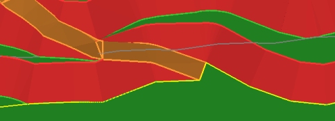
Fixed roads are more freeform and can start and end at any point. They can be straight or curved and will automatically modify the surface to excavate or build up the necessary material to ensure the pit shell's integrity remains intact. For example, the fixed road below starts at a pit base and ends at the first bench upwards but does not interact with the pit design strings:
Evaluating Designs
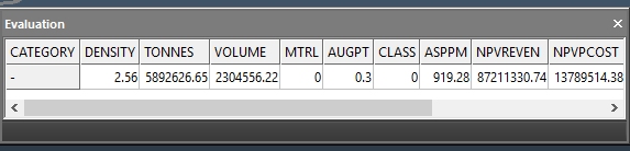
The Auto Pit Design panel can automatically or manually evaluate your design surface against the planning model associated with the current pit. The evaluation will be performed against the closed volume that results from the intersection with the calculated design surface and the topography assigned to the pit. Results are categorized according to the evaluation legend defined for the pit, for example:
Design Data & the Reserves Workflow
The design surface (the "Phase DTM") created using the Auto Design task is stored as a phase DTM when the Auto Design task is saved. This allows you to, for example, generate phase solids and blocks based on a phase surface that includes planned in-pit road geometry and ensure that your designated phase solids are created from a pit that honors slope region and other operational constraints.
Activities
Configure Auto Pit Design General Settings
To configure general auto pit design settings:
-
If you wish to use your resulting pit shell as an input to the Reserves Workflow, you will need to select aPitandPhaseto specify a pit phase DTM that will be used to construct phase solids and other downstream block activities.
This is the surface that is create (and subsequently updated) by the Auto Design task, allowing you to consider your road and constrained pit geometry during reserves evaluation.
If a pit phase already exists, it can be selected using the same lists, with the latest available data for that pit and phase combination being displayed automatically in the Pit Design 3D window.
Note: If you have not already defined phase details (as part of the Define DTMs task), neither Pit nor Phase lists are enabled.
-
You can set up one or more design Scenarios for each Pit and Phase combination.
Note: Settings displayed on the Auto Pit Design, Conditioning and Berm Taper panels are specific to each scenario. It is easy to clone scenarios to test specific parameter changes on designs. You can find out more about pit design scenarios here.
-
Choose a Design Direction.
-
To design your pit from the uppermost bench downwards, choose the Top-Down option.
-
To design your pit upwards from the base, choose the Bottom-Up approach.
Your choice is typically governed by available pit contours. By default, pits are designed from one or more base strings upwards (that is, the initial contour string represents a pit base).
Note: You don't have to stick to the same direction for all phases - if you want to define phases for the same pit in different directions, you can.
-
Choose Constraining Surfaces
In order to accurately evaluate volumes represented by a pit phase solid (the volume constructed between the upper bounding surface of your pit and the designed pit shell), the design task needs to know which surfaces to use.
By default, the upper bounding surface is the topography file specified during the Surface Topo managed task on the Setup ribbon. However, you can choose any surface to act as a topography. For example, it may make sense to use the phase design for the previous/earlier phase in the project as the input topography. For example, the volume results could be used as part of a compliance to design OEM activity.
To configure constraining surfaces:
-
If not already visible, expand the Constraining Surfaces command group.
-
Choose your upper bounding surface:
-
Select Default Pit Topography to use the previously defined topography for the pit.
- Otherwise, browse for any surface file.
-
- Optionally, specify a lower constraint, using the Contact option. This allows you to select a wireframe surface file (either in the project or on disk) to further constrain your data. Data will not be generated below this surface.
Configure Adaptive Roads
Adaptive roads confirm to the contours of your pit or dump design strings and are ultimately used to modify the pit wireframe surface to embed the road in a realistic manner.
- If not already expanded, expand the Adaptive Roads command group.
-
To edit a previously-created road, expand the Name list and pick a road. All road names for the current scenario are listed. You can also select a road by clicking the pointer button and selecting a road string already displayed in the Pit Design 3D window (then click Done).
Alternatively, click New and enter a new Name to add a new road to the selected phase.
Note: Delete an existing road by selecting it and clicking Delete.
-
By default, the road is enabled as Use is checked. You can uncheck this box to remove the road from the design (and re-enable it later if needed).
-
If defining a new road, choose if the adaptive road will initially move up or down the pit or dump in a Clockwise or Counterclockwise direction (imagine a view directly above the pit shell, looking down.
Warning: This direction can't be edited for an existing road. To change the direction of an existing road, it is necessary to delete the original road and recreate it using the other direction option. These options are not available for existing roads.
- Choose the maximum possible Gradient for the road, in either degrees, as a ratio or a percentage value.
-
Choose the berm Width required for the road. Initially you must set a constant width for the road. Once the road has been Recalculated at least once, you can adjust the width of the road along its length from start To the end point. The To field is only enabled for existing roads.
Optionally, for an existing road, click Edit and define a 2-point distance along the section of road you wish to edit. On selecting the second point, the road width will be adjusted accordingly, honouring other design parameters.
In the example below, the road width below the switch is altered from 10m to 5m:
Original road
Set width = 5m
Apply
Tip: If you intend to use a variable road width for a new road, enter the Width first, then Recalculate, then enter the To value and Recalculate again.
-
Configure the Entry Distance. The road entry taper is an important aspect of adaptive road design and the specified distance governs at which point along the starting berm the taper begins.
A larger value will (if it is possible to fit it in) create a more gradual transition from the 'raw' pit profile and the road entry, whilst a zero value, for example, will mean that a constraint string for the starting elevation will be used explicitly to shape the road entry (which isn't initially useful but can be modified to craft a custom entry shape - see below).
For example, in the image below, the values of zero (0), 20m and 40m are used for the same bottom-up adaptive road. The constraint string at the road start elevation is highlighted in yellow:
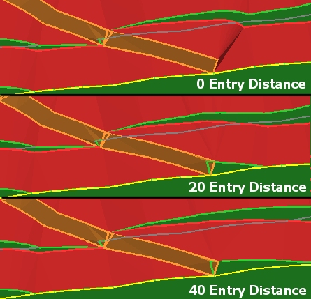
Whilst the 0m open pit example is impractical as it stands, the constraint string can subsequently be used to craft the road entry to any custom shape. For example, by manipulating the corresponding pit constraint string of the first example, more controlled road entry can be achieved e.g.:
- Bench
transitions determines how road segments
align, and how this alignment affects the pit or dump around them when
they transition between benches. The Offset
road ends check box can be set independently for each road:
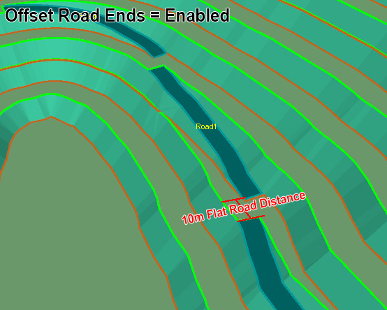
- If Offset road ends is checked, designs start the berm from the inside of the road on a bottom-up design, or the outside on a top down design. This means that the next road segment is offset by the taper width, which can be useful for providing access to berms or lifts. However, it can potentially cause discontinuities in the road that are unwanted.
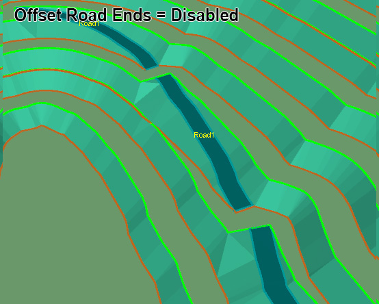
If Offset road ends is unchecked, road segments are aligned (i.e. not offset).
Here's an example of offset vs. non-offset road segments for the same taper width (a 10m flat road distance has been applied as this provides access to the berms or lifts in the offset case:
Note: Whichever way you manage road segment ends, you can choose if and how the pit or dump is modified to accommodate the settings. For example, by disabling the Offset road ends check box, this may mean a road segment has to be oriented differently, meaning the surrounding berm/lift or face should be modified to provide a more natural result. In order to allow the roads to align, the faces on the side of the road may be shallower than specified by the slope regions (they will never be steeper than the current slope region definition allows).
-
You can also choose to perform automated Kink Correction when calculating design strings (and the resulting surface and volume). This setting lets you choose if and how the pit is modified to accommodate road changes.
Because each crest string is generated from the previous road profile and berm, the step between the road end and the berm can cause a discontinuity (kink) in the next crest string, for example:
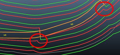
A "kink" may also show up with offset roads which use asymmetrical berm widths and/or different road widths.
If kink correction is checked, you can choose how the correction is applied:
-
None - don't adjust the berm or face to provide a smooth transition between benches. In this example the inside berm or lift width is 1.5, outside width is 5, and road width is 10:

-
By berm - extra width is added to the inside or outside berm to get the outside berm or lift to align with the road end and avoid the discontinuity, and therefore avoid the kink, for example:

-
By face - the next face angle alongside the road is made shallower to push the crest string out and correct the kink, e.g.:

Tip: You can also reduce the impact of bench transitions using global settings such as those found on the Conditioning tab, such as filleting. The settings outlined here are road-specific.
Note: Changing values in the Bench Transitions control group triggers an automatic recalculation of design strings.
-
-
You can add a Switchback to an existing road (if creating a new road, click Recalculate to apply current settings and generate a road item, then you can access the rest of the panel).
Road switchbacks are controlled by the following settings, which apply to all switchbacks on the selected road:
-
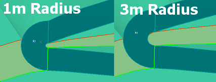
Radius: define the turning radius of the switchback. Increasing the radius will give rise to a switchback covering a larger area. The default value is zero, meaning there will be no internal turning radius, but the outer radius will sweep around whilst maintaining the expected road width and other constraints:
-
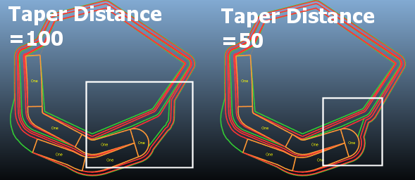
Taper Distance: the taper distance for switchbacks is controlled independently of roads. Use this setting to apply a taper distance to the next switchback (or to an existing one by clicking New Switchback and clicking in the same place as the switchback you wish to modify).
-
Add Switchback: as with the Ramp Layout task, you can add a switchback at any point on the current road segment. Gradient and final elevation settings will continue to be honored where possible. You can also remove any previously-applied switchback from the current road segment.
-
Remove Switchback: remove an existing switchback. Left- or right-click close to the area of a switchback (tip: if multiple switchbacks exist in the same area - zoom in first). Design strings are recalculated automatically on removal of a switchback.
-
-
For a new road, you need to set a start position. Once a road exists, you can reposition its start point and end elevation. How Road Endpoints are modified is affected by your choice of bottom-up or top-down design.
-
For new and existing roads, interactively pick the start position by clicking Choose Start Point and left- or right-clicking a position in the Pit Design 3D view.
Tip: To align your road with a particular design string, Recalculate your design strings and use the filters at the bottom of the screen to show only Design Strings. This can make it clearer to right-click (snap) to a design string on a target level.
-
Once a road exists, its Lower Elevation and Upper Elevation values appear. You can edit these values to fix the start and end points at the desired elevation, either by manually entering a numeric value, or by selecting a bench reference level from each drop-down list. You can also pick a location in the 3D view either by left-clicking (which takes the elevation of the currently active 3D section) or right-clicking to existing data.
Note: The Lower Elevation cannot be above the Upper Elevation.
-
-
Once all adaptive road settings are in place, click Recalculate to create new design strings with updated road properties for your pit or dump design.
-
Save your project.
Configure Fixed Roads
Fixed roads are formed by honouring the specified gradient and start point. The direction is specified interactively.
Initially, a string is drawn to the screen which you should review and edit before you Recalculate your new design strings. Fixed roads are simple to add and remove, and there is a suite of commonly-used string editing commands that will help you construct the most practical access road.
In fact, any string editing command in Studio can be used to modify a fixed road string. Providing the result is possible to use (i.e. a pit can be sensibly constructed to honour start, gradient and other constraints), the resulting design strings will accommodate the fixed road, including all benches above/below the design item (depending on the direction of your design).
Fixed roads will be positioned either through the addition of material (embankment) or excavation (box cut). All pit constraints will be honoured. See Road Design Tips for more information on the most effective use of these commands.
To configure a fixed road:
-
If not already expanded, expand the Fixed Roads command group.
-
To define a new road, click New and enter a unique Name. Alternatively, pick an existing road from the list.
Tip: You can also pick a road interactively in the Pit Design 3D window.
-
By default, the road is enabled as Use is checked. You can uncheck this box to remove the road from the design (and re-enable it later if needed).
-
Define a Gradient for the road in degrees, as a ratio or as a percentage, and will be a primary maximum constraint (it will not be exceeded for operational reasons).
-
Set the Width of the fixed road. The width is applied across the entire fixed road.
-
Choose Start Point and click in the 3D view (right-click to snap to existing data) once to define the start of the road, and again to denote the end position and elevation.
-
Use the Edit Centerline commands to fine-tune the centerline of the fixed road. You can also do this after road calculation or before.
Delete: remove the currently active fixed road centreline string from the collection.
Move Centreline: enables the move-strings2d command. The active fixed road centreline can be repositioned within its current elevation and/or rotated using the modifier controls. It is possible to move a fixed road so that either the start, end or both points cannot be integrated into the design. In this situation, the Output window will highlight the situation.
Insert Curve: the insert-curve command is really useful for modifying a fixed road string, particularly if a smooth curve is required.
Move Points: enables point editing mode to allow you to modify the active fixed road string vertices. This command responds to both left-click (on-section) or right-click (snapping) modes. It is often useful to snap a start or end point to a known crest or toe string, for example. Cancel the command when you're finished. More about move-points-mode...
Insert Line: modify your fixed road centreline string by inserting a new line segment. This can be used to either increase or decrease the complexity of the string. More about insert-line...
Insert / Delete Points: runs the insert-points-mode and delete-points-mode commands respectively. You will need to Cancel these commands when you're finished.
Note: The commands shown are shortcuts to other design commands found elsewhere in the system. You can use any string editing command to alter the centerline.
-
Once your centerline is as you want it, click Recalculate.
-
Regenerate your pit or dump surface and review.
-
Save your project.
Configure Outputs and Visual Settings
Various tools appear at the bottom of the panel. They are used to recalculate design data and set visual formatting options, and can be applied in any order:
-
Show Pit Constraints – adding constraint strings is a simple case of selecting 1 or more Phase Shell Contours (for pit designs) or dump profile perimeters (for dump designs), then clicking Add selected string(s).
-
Show Fixed Road Centrelines—this option is only available if at least one fixed road has been added to the scenario. If so, the status of this setting determines if all fixed roads are displayed or hidden.
Whilst you can't hide and show individual fixed roads, you can enable or disable fixed roads independently via the Fixed Roads command group.
-
Object Generation Options
These options relate to which optional data is created when scenario results (design strings or phase surface) are generated. By default, these options are unchecked.
-
Mark Design Strings Outside Constraining Surfaces
Select this option to format the string data above and below the assigned topography and/or contact surface independently. This is a useful method for determining where pit geometry such as roads intersect with the surface (e.g. for setting an upper road elevation) or where a road should terminate at the topography surface as entry point to a dump.
This setting is only applied when new design strings are generated using the Recalculate button (see below).
Example of a pit design with strings formatted above the topographyNote: Generated design string data contains an INSIDE attribute, set to 1 or 0 depending on whether the string data that is generated is within the pit or outside it. This attribute can be used for filtering, for example.
-
Create Surface Intersect Strings with Wireframe Generation
If enabled, will automatically generate a contact surface and/or pit rim string that aligns to the intersection of the specified surface(s) and generated design surface. This is applied when the Make Design Surface button is clicked.
Note: these additional design string data representing intersections will have a "CONTACT" value for the TYPE attribute.
To access this setting, either a topography or Constraining Surface must be specified for the current pit.
The image below shows a generated pit rim string with differentiated pit design strings and a transparent topography (enabled using the Pit Data control bar).
-
Combine Design Surface With Constraining Surfaces
A useful option if you wish to generate a design surface that is merged with the assigned topography or contact surface (or both, to create a pit shape between the two).
To access this setting, either a topography or Constraining Surface must be specified for the current pit.
If selected, the Make Design Surface command will automatically intersect the generated pit or dump surface with the nominated topography. For example, the top image shows automated pit design output with this option disabled, and the bottom with the option enabled:
The same principle applies to dump designs, for example:
Note that this setting has no effect on design string generation.
-
-
Show Design Strings and Recalculate—design strings can be hidden or displayed using this check box. This control is only available if design strings have been created at least once within the current project session. Clicking Recalculate will recreate a series of strings representing the pit or dump geometry. This is where the regional parameters (face angles, berm widths), road definition, and constraint strings are interrogated to ensure they are honored during pit string generation.
All defined lifts or benches will be used to project the pit design upwards or downwards, although if a topography is specified, additional visualization options become available (see above) and will be applied when design strings are recalculated.
-
Show Design Surface and Make Design Surface—once a suitable set of design strings can be seen in the Task window, click Make Design Surface to create a DTM that will represent either the pit shell for the Pit/Phase combination, or the dump shell comprising all defined lifts, roads etc. Once generated, you can show or hide the surface. Make Design Surface will always utilize the latest design strings to generate a pit surface. For pit designs, the generated shell is accessible by the Reserves processes (Add DTMs, Create Phase Solids etc.) when the Auto Design task is saved.
This command is also available on the Auto Design toolbar.
Note: If Auto Evaluation is selected (see below) evaluation results will be output the Design Evaluation control bar, updating any existing values in line with any changes in the automatically-created design surface. Selecting this command will clear any existing evaluation results from the Design Evaluation control bar (see below).
-
Show Design Solids—check to display the enclosed volumes for the selected design. This check box is only available if an automated design has been previously created.
-
Evaluation settings
These options become available once design strings exist. , and a topography has been assigned to the pit or dump.
Note: If no topography is specified for the current pit, evaluations are based on volumes created by closing the uppermost design string.
Pit volumes can be reported by category and/or per bench and dump volumes by lift:
-
Auto Evaluation—if checked, evaluation results (representing the volume that results from an intersection of the generated design surface and topography assigned to the selected Pit) are output to the Design Evaluation control bar each time you recreate the design surface.
-
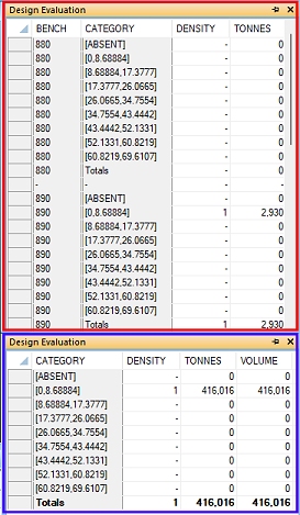
Report by Bench—if unchecked, summary evaluation results (per evaluation category) will be displayed when the Evaluate button is pressed (or a surface created and Auto Evaluation enabled). If checked, the output report will include per bench and per category results.
For example, the image below shows output with the Report by Bench option enabled (red boundary) and with it unchecked (blue boundary):
You can also use Evaluateto manually trigger an evaluation of the current design surface/topography intersecting. This button and the Auto Evaluation option is inaccessible if no design surface exists yet.
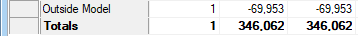
Where pit volume is detected outside of the model, it will be reported in its own table row, e.g.:
This command is also available on the Auto Design toolbar.
-
-
Show Pit Data Objects
This section controls which of the key elements of your design are displayed in the Pit Design 3D view. Checking or unchecking options doesn't unload data, it just controls whether it is displayed.
-
Show Topography—only available if a topography is associated with the selected Pit. Toggles the display of the specified topography surface file.
-
Show Planning Model—shows or hides the planning model associated with the current pit. By default, an intersection of the model and the active 3D section is displayed, at the level set in the Bench Sections toolbar.
Tip: Use the Bench Sections toolbar to show other model sections within the current pit, exposing higher grade blocks which make extraction viable.
-
Show Contact Surface: Only accessible if a Contact surface (Constraining Surfaces group) is specified. Toggles the display of the contact surface wireframe.
-
Show Phase Shell Contours: Hide or show pit contour strings.
Note: Contour strings are created using the Shell Contours task.
-
Show Slope Region Strings—if slope region boundaries have been specified using the Define Slopes task, you can toggle their display here. If no slope region boundaries exist for your project, this option is unavailable.
-
Create Overlays: Typically, auto desisn data is automatically unloaded when the task is closed. However, you can create persistent and reusable 3D window objects and overlays from any generated design data if you want. Selecting Create Overlays displays the 3D Objects screen, from which you can select any loaded data object to convert into an object and overlay that will persist when the design task is closed. This could be useful for reporting or additional volume calculations (such as cut and fill) for example.
-
Related topics and activities