Create Vein Surfaces
To access this screen:
- Activate the Geology ribbon and select Surfaces >> Vein.
- Enter "vein-from-samples" into the Command Line.
The Create Vein Surfaces screen is the interactive interface for the vein-from-samples design command, used to model linear, continuous structures representing vein or vein-like structures according to the presence of Positive and Negative Samples. See Vein Modelling.
Note: The Create Vein Surfaces screen can be used in conjunction with other application functions.
The screen is split into setting categories. Many sections can be expanded or collapsed to make it easier to define settings for a modelling run. Expand or collapse a screen section by clicking its title bar, for example:
The following sections are available:
-
Data Selection: Choose a loaded drillhole object and a value to model. Typically, this is a categorical model representing a linear structure throughout the sample data. This area also provides useful 3D section tools to let you view your sample data in an appropriate way before reviewing and editing hangingwall (HW) and footwall (FW) points.
Data can be preselected before displaying the Create Vein Surfaces screen. See Select Data for Implicit Modelling.
-
Edit Samples: Adjust sample HW and FW points, including reversing and ignoring samples to encourage a modelling outcome. This section also includes global settings to determine how sample gaps are treated (the Create Vein Surfaces tool expects a single continuous sample). End-of-hole data options are also available. See Edit Vein Model Samples.
-
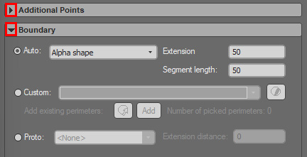
Additional Points: Encourage an expected surface or volume shape by adding HW and FW samples. You can also add additional samples to the trend surface; this is the surface generated throughout the midpoint of positive samples. Adding points can influence the shape of both HW and FW surfaces. See Add Extra Vein Points & Intervals.
-
Boundary: Constrain your output shape(s) using a boundary. This can either be calculated automatically in relation to the exterior hull of your loaded sample data, or using a custom string outline or block model prototype. See Boundary Options.
-
Faults: Model fault blocks by introducing wireframe sheets to your modelling scenario. Faults can fully or partly intersect the drillhole data, and you can optionally automatically extend fault wireframes to ensure a clean intersection with the data extents. See Model Faults.
-
Controls: Define global modelling settings that constrain the thickness of an output volume and the density (size) of output wireframe data. See Manage Volume Thickness
-
Output: Choose the data to create; HW, FW or a combined volume. You can also generate a trend surface and a string representing the boundary of the output vein data (which can subsequently be used with modification as an input boundary to refine the overall shape).
A batch run option is available; recreate previous settings for each Column and Value combination. This can be useful, for example, to assess the sensitivity of a parameter to the output vein shape. See Process a Batch of Vein Models.
If you define modelling settings and close the Create Vein Surfaces screen, those settings will be reinstated when the screen is next displayed. This applies to the current project session only.