
Create a Vein Model
The Create Vein Surface screen is the interactive interface for the vein-from-samples command.
Both are used to model linear, continuous structures representing vein or vein-like structures according to the presence of Positive and Negative Samples.
Throughout this help topic, the following acronyms are used:
-
"HW" — Hangingwall. The initial surface of a vein model transected by a drillhole.
-
"FW" — Footwall. The final surface of a vein model transected by a drillhole.
Note: To find out more about creating a batch run of vein models, see Process a Batch of Vein Models
To create a single vein model based on loaded drillhole data:
-
If required, preselect drillhole data in any 3D view. See Select Data for Implicit Modelling.
-
Display the Create Vein Surfaces screen.
-
In the Data Selection area, select a loaded static Drillholes object containing samples to be used for vein modelling.
Note: if the selected drillhole object is subsequently unloaded, it and all settings relating to it are removed from the screen.
-
Select the Column (also known as the 'attribute', 'property' 'key field' or 'field) containing a value to be modelled. This will contain distinct numeric or alphanumeric values, with each representing a particular domain to be modelled.
-
Select the column Value that represents the category to be modelled. All unique values of the selected Column are listed alongside their respective default legend colour.
Note: you are warned if the selected Value has over 100 unique values. You can still continue if you wish, but system performance may be degraded.
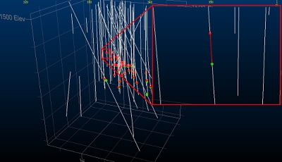
Once a value is selected, samples that match it are highlighted in the 3D window to show the positive intervals.
Symbols are added to each interval's FROM and TO positions. This indicates the 'positive' intervals to be modelled. For example:
-
Data can be modelled only if it is Selected and/or Visible, using a combination of settings.
-
If Selected is checked:
-
If no data is selected, everything is modelled.
-
If data is selected, only selected holes are modelled.
If selected is unchecked, all data is modelled regardless of data selection.
-
-
If Visible is checked, only drillhole data that is visible is used for modelling, otherwise data is modelled even if it is filtered from the view.
-
-
Define your implicit modelling section using a combination of tools in the Section Controls and Best Fit Plane groups.
By default, the normal direction of the output wireframe data is orthogonal to the Best fit plane. This is calculated by one of the following methods:
-
Automatically (Auto) as a mean plane passing through the positive intervals of the sample data.
-
Using the current 3D window section definition to guide normal creation (Current section).
You can adjust the current 3D section using the tools shown in the Section Controls group, some of which are replicated on the 3D View ribbon (where more options can be found for section management).
Tip: Enable Auto look to automatically align with the positive samples corresponding to the selected Value. This will happen each time the Value changes.
-
As a Custom section, by setting any Azimuth and Inclination values. This does not affect the current default section in the 3D view.
-
-
Manage Contacts if required. This lets you fine-tune the contacts used in modelling:
-
Expand the Manage Contacts group, then review controls from left to right.
-
Select intercept point colours using the HW colour and FW colour lists if required.
Note: The contact management buttons and point indicators update to use the selected HW and FW colours. If you change either colour, the related buttons update dynamically.
- In Enable / Disable, choose On or Off for HW or FW, then pick one or more points in the 3D view to activate or deactivate those points. Deactivated points are not considered during implicit modelling.
- To deactivate gap-related points, choose Gaps: Off, pick one or more points in the 3D view, then click Done to complete the command mode.
- To deactivate all gap-related points in the current context, click All Gaps Off. In practice, this ignores intervals with gaps when modelling.
- To reactivate all points globally, click Enable All Points.
-
In Swap, use Swap HW / FW to swap selected interval points, or Auto Swap All to reapply automatic assignment.
Note: When you change the data context (drillholes, modelling field) HW and FW points are automatically set to a default alignment (which depends on the orientation of the modelling section plane).
- Click
 Done to exit the current editing mode.
See Edit Samples.
-
-
To insert HW, FW Additional Points into the data set before surface computation, or to insert new 'dummy' intervals containing both HW and FW:
-
CheckAdditional points (disabled by default).
-
If required, select an existing points Object to host the additional data. Additional points are not added to the selected Drillholes object.
-
Use the tool group provided to add new HW, FW, trend points or dummy intervals.
Use the section editing tools to set the 3D section beforehand (to make sure you are adding points at the expected position.
Tip: Enable the display of the 3D section and use the Snap to Plane command to set the position in relation to other HW and FW points. The Interactive Section Editor is useful here too.
-
If a loaded string object's vertices represent HW or FW additional points, pick Add selected strings as additional HW points or Add selected strings as additional FW points, then pick a string in the 3D window. This is useful if you already have additional points data saved as separate string objects.
-
-
In the Snapping group, choose how Collar Points and EOH Points (end-of-hole points) are considered during vein modelling.
-
Choose Snap to force the modelled vein surface to adhere to the collar or end-of-hole position if the modelled sample contains a collar or EOH record. In this scenario, the surface cannot pass above the collar position where the drillhole intercepts the model.
-
Choose Ignore to treat the collar or EOH position as absent if the modelled sample contains an initial or terminal record. In this case, the surface can pass above or below the start or end of a hole at the point of intersection.
-
Choose Pass above (Collar points) to permit the surface to occur above the collar position (if one is located in the sample) but not below it (if the surface would naturally be generated below the collar, it is moved up to be coincident with the collar position.
See Edit Samples.
-
-
Define the Boundary to constrain the output surface(s):
-
Expand the Boundary group.
-
Choose a boundary method:
-
Choose Auto to use the hull of the loaded drillhole data to determine the shape of the output surface data in one of two ways; Aligned Square or Alpha Shape. If selected, an Extension distance lets the output surface be generated beyond the hull up to a fixed limit.
If using an Alpha Shape boundary, set the Segment length to control the granularity of segments around the edge of the output shape.
-
Choose Custom to use an outline string to constrain the generation data. Optionally, pick an existing string or digitize your own. One or more perimeters can be selected.
-
Choose Proto to pick an existing block model object. The cuboid hull of the block model constrains output wireframe data generation, with an optional Extension distance.
See Boundary Options.
-
-
-
If you have fault wireframes representing discontinuity zones, you can model independent fault blocks instead of a single, continuous surface or volume. To model fault blocks:
-
If not already loaded, load wireframe data and display it in the 3D window. This data represents the faults upon which discontinuities in the resulting implicit model are computed.
-
Expand the Faults group.
-
Enable Use faults.
-
Expand Fault surfaces and pick a wireframe object containing one or more fault sheets.
-
If the loaded wireframe object contains a key field that uniquely identifies fault sheets, select a Fault ID column. If no column is selected, all wireframe data is considered as a single, continuous fault sheet.
- You can generate Scissor faults if you wish.
If checked, faults are extended beyond the nominated boundary and can terminate within a fault block, whereupon the throw of the fault is gradually reduced to zero over distance. For example, in the image below, the green and red blocks are fully isolated, but the green block is partly faulted as scissor faulting is permitted:
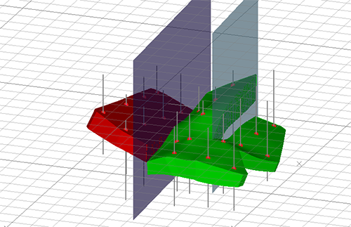
- If unchecked, fault wireframes must fully transect the exterior hull of the positive drillhole samples (or another fault sheet) in order for fault blocks to be created. Scissor faults will not be created.
-
- Define the remaining surfacing controls to manage thickness, pinching out and output data resolution, using the Controls group.
Set the Minimum thickness of the vein. This can be interpreted in one of two ways:
If Expand to is selected, the output vein will never be thinner than the value set and no pinching out (see below) will occur. Where you're confident of a continuous output, this can be a good option to enforce a single, uninterrupted strata.
If Remove below is selected, if the output vein true thickness falls below the value set, material is removed, created a void. This occurs regardless of the Pinch out setting.
Set the Maximum thickness by enabling the option and defining a value. This constrains the maximum thickness of the output vein shape. This can be used to constrain 'blow out' of shapes where there are significant interval depths between neighbouring samples.
Choose a Boundary thickness. This is the value at the edge of the output model you want to achieve. This can be useful to reduce the gradual reduction of thickness as the model moves beyond the terminal positive samples, but is still within the modelling boundary.
- Choose Output options:
Choose to Generate a Hanging wall, Foot wall or Both. If Both is selected, HW and FW surfaces are joined to create a watertight volume.
Tip: An output volume includes a SurfaceT attribute with either a FootWall, HangWall or Connection value. Filtering out Connection leaves isolated hangingwall and footwall surfaces.
- Choose where to store output Vein surface; enter a new name to create a new object, or pick an existing object to overwrite.
- Sometimes, it is useful to generate a Trend surface. This can help you to visualize issues caused, for example, by incorrectly reversed samples or errant HW and FW positions. If checked, a trend surface wireframe is generated with the selected object name.
- Generate a hull string that represents the intersection of the active 3D section and the generated surface or volume by enabling Boundary. Create a new object name or pick an existing object to overwrite.
- If you wish to generate Contact points data separately, select a points object using the list provided, or enter the name of a new points object to create.
After setting up formatting to show vein surface(s) and trend surfaces as an intersection in a custom colour, you can retain this formatting for recomputed data by checking Retain output formatting. This means you don't have to keep reapplying my formatting settings when experimenting with the various controls.
If unchecked, formatting is reset each time you recompute a vein model.
-
Generate your vein model:
-
Select Update Vein to overwrite an existing vein model (if one of the same name exists). If the current Vein surface object doesn't exist, this is the same as Compute New.
-
Select New Vein to generate output without overwriting data of the same Vein surface name. If a duplicate object name is detected, the output data will contain a suffix to make it unique.
-
Related topics and activities
-
Create Vein Surface (screen)