
ESTIMATE: Unfolding
To access this screen:
- Display the ESTIMATE screen and select the Unfolding tab.
ESTIMATE is an interactive version of the ESTIMA process, with additional functions provided by INDEST.
Define sample coordinate unfolding parameters for grade estimation using ESTIMATE here. Typically, unfold parameters have been defined using the Unfold Wizard beforehand.
All settings on this screen are optional. If you don't need to unfold input data, click Next to move to the Search Volumes screen.
To define data unfolding settings:
-
Display the ESTIMATE screen.
-
Select the Unfolding tab.
-
Define the Unfold Strings File produced by the Unfold Wizard operation. This contains validated hangingwall and footwall strings.
-
In the Fields section, pick the fields of the Unfold Strings File (see above) that identify key data and data switches:
-
SECTION—the field containing the section identifier. This is a numeric value identifying each section.
-
BOUNDARY—the field containing the boundary (HW/FW) identifier. This is a numeric value that identifies the hangingwall and footwall strings. A value of '1' represents the hangingwall strings, and a value of '2' represents the footwall strings.
-
WSTAG—the field containing the within section tag identifier. This is a numeric value identifying each tag.
-
BSTAG—the field containing the between section tag identifier. This is a numeric value identifying each between section tag.
-
-
In the Parameters section, the values set in the Unfold Wizard display. This includes the Link Mode that determines whether within section or between section tag strings are used:
-
Choose Use Within Section and Between Section tags to utilize the tags of the input Unfold strings file during estimation.
-
Choose Do not use any tags to ignore tag information in the input strings file during estimation.
-
-
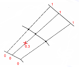
Choose the Unfolded Coordinate Type to define the scaling applied to each axis in the Unfolded Coordinate System (UCS). This defines the relative position of the associated unfolded data for each UCS axis (UCSA, UCSB and UCSC).
-
Normalised (between 0 and 1)—a normalised coordinate uses a value between '0' and '1' to represent a position on the applicable axis. This is the distance as a proportion of the total distance along the axis, for example:
-
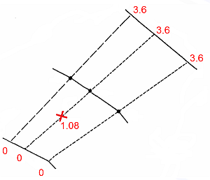
Adjusted (normalised * av. length)—the normalised coordinate value multiplied by the average length of the applicable axis, based on data from all sections. This is shown in the example below:
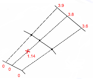
- True Length—the true length coordinate
is the distance from the origin of the applicable axis in
the Unfolded Coordinate System, measured in standard World
Coordinate System units, as shown in the example below.
- For UCSA, this provides a measure of width, or true width.
- For UCSB, this is the distance along the dip-direction of the strata.
For UCSC, `adjusted' units are used by default. This is generally satisfactory as the UCSC coordinate should correspond to the direction of the fold axis.
World X / World Y / World Z Coordinate—the value on an axis in the Unfolded Coordinate System corresponds to one of the standard (X,Y,Z) axes in the World Coordinate System.
-
-
Pick the Plane in which sections were defined. By default, this is perpendicular to the plane of the strike string:
-
If the strike string is defined using a horizontal plane, choose Vertical section.
-
If the strike string is defined using a vertical plane, choose Horizontal plane.
-
-
Set a Tolerance value, defined as a proportion of the UCSA width, which allows samples which are just outside the hangingwall or footwall to be unfolded.
-
If a Tolerance value greater than ‘0’ is set, then one of the following conditions is applied to the UCSA value. These options are defined in terms of the Normalised mode:
-
1: No restriction on UCSA—values can be less than ‘0’, or greater than ‘1’.
-
2: UCSA <= 1—values calculated as greater than ‘1’ are reset to '1'.
-
3: UCSA >= 0—values calculated as less than '0' are reset to '0'.
-
4: UCSA >= 0 and UCSA <=1—values calculated as less than '0' are reset to '0', and values calculated as greater than '1' are reset to '1'.
-
-
-
Pick a UCSB Origin Tag Number. This allows you to specify the origin for the UCSB coordinate by selecting a Between Section string.
-
Choose the numeric value that defines the hangwall and footwall strings:
-
Hangingwall BOUNDARY value—specify the numeric value that identifies the hangingwall string.
-
Footwall BOUNDARY value—specify the numeric value that identifies the footwall string.
-
-
Click Next to proceed to the Search Volumes screen.
Related topics and activities