
Wireframe Shading Methods
The Wireframe Properties screen is used to format the appearance of wireframe overlays in 3D windows.
These options determine the rendering method used to display wireframe data.
| Shading Mode | Comments | |
|
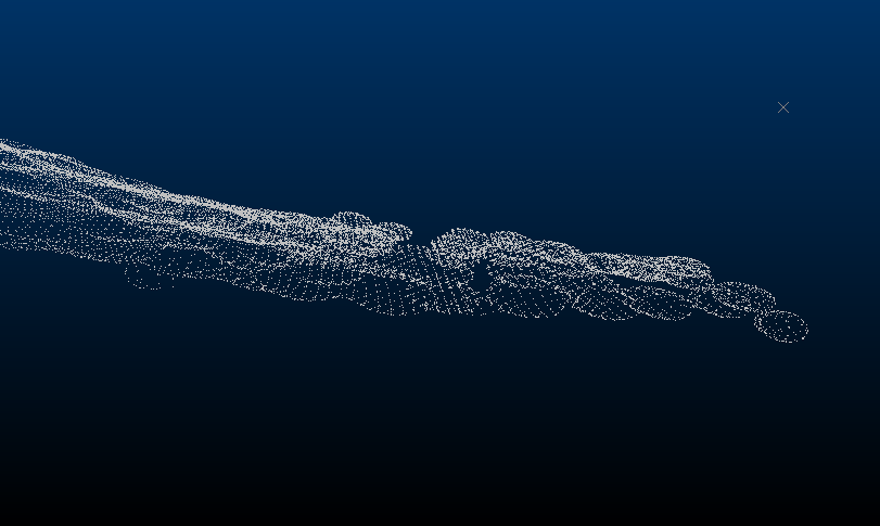
Points | Display the current wireframe as vertex data only. This data is held in the "wireframe points" file, typically ending with a "pt" suffix prior to the file extension. |
|
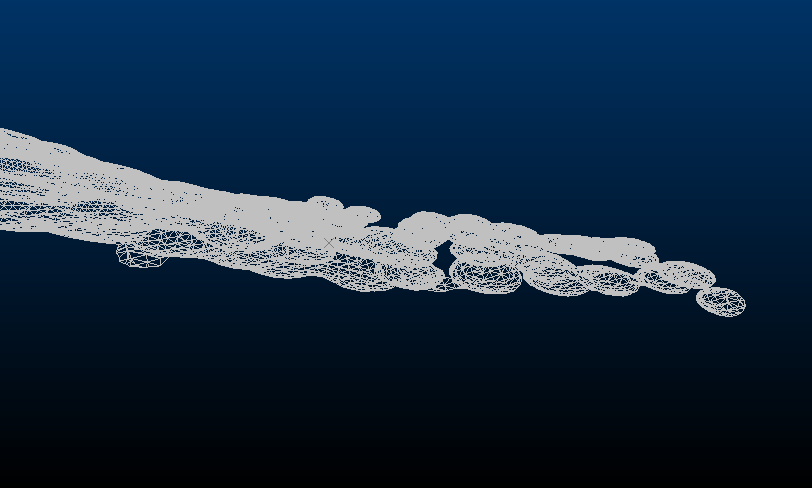
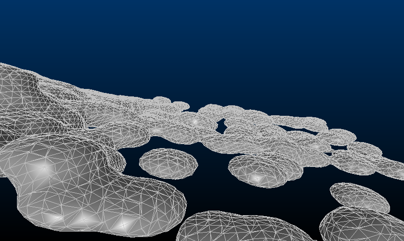
Wireframe | Display only the wireframe edges. |
|
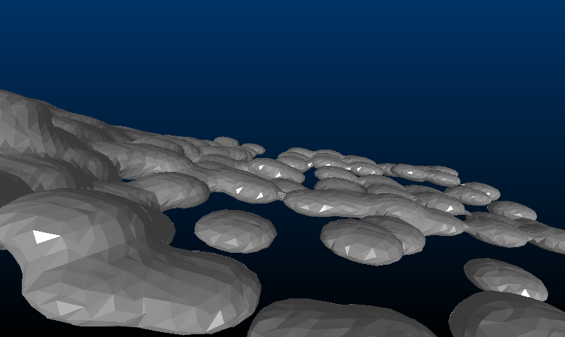
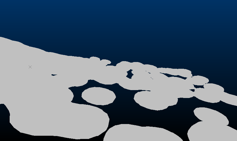
Flat | Shade wireframe triangles distinctly and individually. |
|
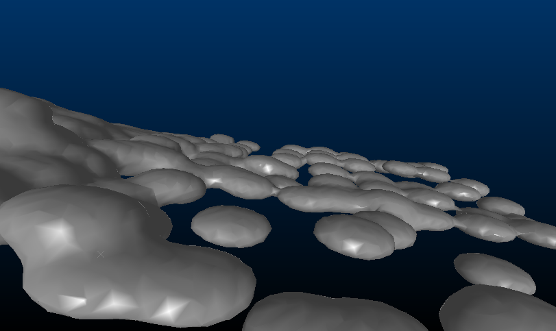
Smooth | Interpolate (dither) the shading between wireframe triangles. |
|
Highlighted Edges | A combination of Smooth and Wireframe modes. |
|
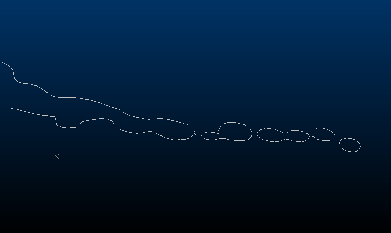
Intersection | Display the cross-section of the wireframe with the current (active) section, or the Intersection Section, which can be any loaded section definition. |
|
Unlit | Available for Flat and Smooth modes, if Unlit is checked, a solid colour (no environmental lighting) is used to render the wireframe data. |
|
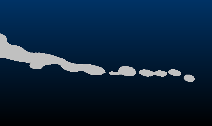
Filled Solid |
This mode can be used with Flat, Smooth, Highlighted Edges and Intersection, allowing solid outlines to be filled. It creates a filled intersection or caps the ends of wireframe data that has been clipped in the view. Note: This setting is currently offered as a preview only. We are planning further work on ensuring the display is correct for multiple overlapping volumes. Note: This setting applies only to solid wireframes. Results may be unpredictable or unsupported for surfaces or open volumes. |
|
3 Way Intersection | Only available for 3D Variogram window data. Selected by default for all generated isosurfaces that support a variogram map display (using the Advanced Estimation - Investigate Anisotropy screen). The selected wireframe surface is shown as an intersection with all 3 displayed sections. This differs from the standard Intersection option (see above) which will only display an intersection with the currently active display section. |
Related topics and activities