
Network Dependencies
To access this screen:
-
Display the Edit Dependency Rules screen and select the Network Rules tab.
A schedule is of little use if it does not honour your operational haulage capabilities. Studio UG understands this and will attempt to ensure the direction and configuration of FXS design string data accurately portrays the flow of activities throughout the schedule.
Note: A road network is configured using the Preparation screen (Roadways tab).
The Network Dependencies screen lets you define rules that describe the progression of activities of the schedule as governed by haulage and other operational capabilities. This analysis is performed between FXS string data of the same dependency layer, and can also link stope activities (CXS or WFM) to qualifying FXS strings below each stope.
Each design definition (Decline, Level Access, Remuck Bay and so on) can be configured to define which other design types it can connect to. This avoids illogical connections (such as drive-to-drive mislinks) and improves processing speed.
Typically, this involves the automatic redirecting and modification of FXS design data represented by the following design definitions. Here are some examples:
-
Decline (for example, the start of the network and access to all level drives).
-
Level drive (second access that connects declines to all ore drives and crosscuts).
-
Ore drive (following access that can also connect to crosscuts).
-
Crosscut (following access that can also connect to ore drives).
The default <Roadway Analysis> rule set displays on the left of the screen. Set the dependency layer to analyse and click OK or Apply. During the next dependency processing run, each roadway is detected and, where appropriate, a dependency is formed with the next logical activity point (that carries a qualifying design definition).
When stope-to-drive linking is used, select an attribute field to represent level matching between stopes and FXS strings. The field name is user-defined and is not restricted to a field called LEVEL.
If more than one qualifying FXS string below a stope matches the selected attribute value, dependencies are created to all matches.
Tip: View and manually edit the direction of FXS design strings using the Preparation panel (Design Direction commands).
How Roadways Analysis is Performed
Roadways analysis results in the determination of a road network based on the most likely downstream activities of a parent activity. The formation of a road network between separate points involves:
-
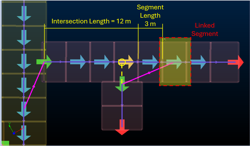
If there is only one segment on the design that is the From position then take that segment. Otherwise:
-
Get the distance from the start of the From design to the intersection point (either real or interpolated).
-
Get the width of the To design definition.
-
Find the first segment that begins after the sum of 1 and 2 along the From design (or the last segment).
-
For example (click to expand):
In practice, this means that you do not need to have coincident or snapped points in your FXS data to encourage a particular development direction. Gaps between strings are interpreted as continuous connections. No manual snapping is required.
Related topics and activities