Planning Dependencies
To access this panel:
-
Activate the Planning ribbon and select Schedule >> Dependencies.
What are Planning Dependencies?
Dependencies are strings created to indicate a scheduling link between activities. For example, a Fill event must succeed the actual mining of the same stope. Hence, it makes sense to create a dependency from the Stoping event to the Fill event.
Similarly, a cross-cut from a decline will succeed the mining of the decline up until the decline reaches the point where the cross-cut starts. A dependency exists, therefore, from the decline segment near to the cross cut.
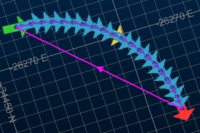
Dependencies control the process of sequencing. Sequencing is the assignment of an order in which activities will be processed and, ultimately, what defines the schedule for your project and how activities take place at the right time, and in the right order.
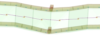
Sequenced Activity Points and Dependencies - The purple line indicates the linear progression from left to right
How dependent activities are linked together can differ within a schedule. For example, you may want multiple activities starting at the same time (that is, they have a start-start relationship), or they can start when another ends (end-start) or some other dependency.
How Dependencies are Applied
Your application processes your data and defines activities based on the presence of automatic and manual dependency definitions. You control both of these dependency types, and a project can have a mixture of both.
These dependencies determine the reliance of one or more activities on other events. Where impossible dependencies give rise to an infinite cycle of events (the dreaded "dependency loop" - see below), each instance is listed and you can use the in-panel tools to correct these problems.
Dependency Repairs
A "Dependency Repair" cycle is performed - automatically - on completion of the dependency processing routine. This facility offers some flexibility in how absolute a search is performed for activity points, and is based on a specified search geometry.
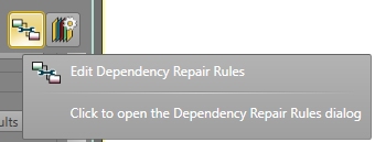
You can set up dependency repair settings at any time using the Edit Dependency Repair Rules screen (say, to experiment with a more or less flexible approach to finding next-in-line activity points within a given distance):
Dependency "Layers"
You can also implement 'layers' of dependencies within the same project. A layer can be considered a category of dependency and can be used to apply the same dependency instructions for a collection of activity points.
This is particularly useful if you wish to create, and then apply, different dependency default settings without having to create projects or minor projects. Say, for example, you wanted to create a specific set of dependencies when progressing your development from one stope to another, which may differ from the dependencies implicit with the task to progress drive development away from a decline. In this case, layers can be used to independently define a distinct category of dependencies.
Layers can be configured to include a custom relationship between predecessor and successor activities (start-finish, finish-finish and so on). Activity delays can also be set independently for each layer.
See Dependency Layers.
Dependency Relationships
Defining two points that have a relationship in the schedule is only one element of defining a sequence. Another is the way in which they are related. This is called the "Dependency Relationship". It is also referred to as a dependency 'Link Type'. In this help file, both terms are synonymous.
Dependency relationships can be set in multiple places:
-
They can be attributed to a Dependency Layer. This is where a default relationship is set, and will be applied in the absence of another instruction, such as that selected during manual dependency or as part of an automatic dependency rule.
-
A default layer-based relationship can be overriden by a relationship set when defining manual dependencies.
The Dependencies Screen
The Dependencies Screen is used to define dependencies between activity points. These points are, in turn, determined by how your design solids have been segmented.
Dependencies are used to determine the sequence of activities within your schedule, and you can display an animation of your current sequence prior to exporting it to DTS for further refinement.
The Dependencies Screen is split into the following areas:
Data Toolbar
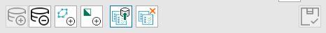
In this section, you can load or unload both activity and dependency data from the primary 3D window. You can also selectively load boundary and solid data if it exists, and save or delete overlay 3D template. On the far right, you can save your Dependencies screen settings.
Schedule Summary
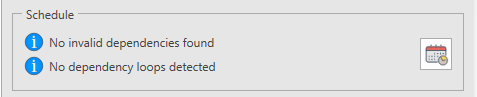
Below the data toolbar, the Schedule group provides a high-level summary of your current schedule health (are there any dependency loops or invalid dependencies that need attention?) and a button to launch the schedule calculator.
Data Viewing Tools
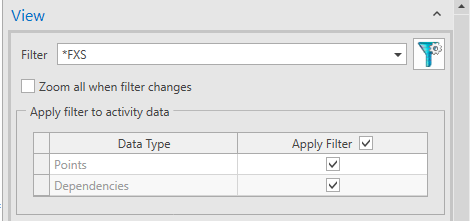
If activity and dependency data is loaded (see Data Toolbar, above), useful 3D view tools are available, including filtering and zooming to quickly isolate and resolve dependency problems.
Rule Based Dependency Creation
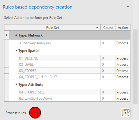
This is where you trigger dependency calculation based on your automatic or manual rules.
Rules are listed by Rule Set, with the number of rules within each set shown as the Count. You can Process the rule (the default setting) meaning the rule will be applied during processing or you can choose to not process the rule (or automatically purge it without processing it).
- Process – Deletes existing dependencies from the rule set (if there are any), then processes the rule set
- Do Not Process – Skips the rule set. If there are existing dependencies for the rule set, they are kept.
- Purge – Deletes the existing dependencies from the rule set, without reprocessing the rule set
This option is only available for rule sets that have Count>0.
If you select Purge and process the rule sets, the Action
will automatically switch to Do Not Process after the dependencies
have been deleted.
If you have made changes to your dependency settings since the last time dependencies were generated, you will be prompted to save these changes. Any errors, warnings and messages are shown here (see "Dependency Processing Messages", below.
This section also provides access to a tool to let you Edit Dependency Rules: set up your automatic dependency logic using the Dependency Rules screen. This panel is also used to access and set up the required filters, layers and search geometries.
Manual Dependency Editing
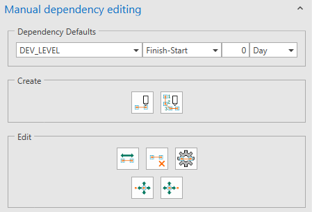
If automatic dependencies need manual intervention (or you prefer old school dependency creation), you can manually craft your dependency strings here, by manually selecting the predecessor and successor points of displayed data.
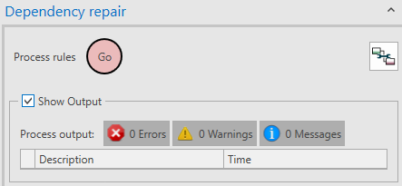
Dependency Repair
Show Dependency Labels
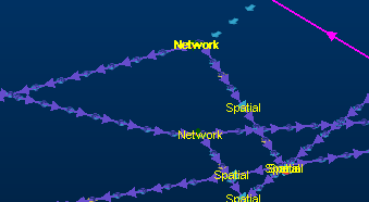
When viewing dependencies in the 3D window after loading data, it can be useful to display labels showing the type of dependency formed:
-
Is it a spatial dependency created because of the proximity of activity points?
-
Is it a network dependency formed by the direction and connection of design data?
-
Is it an attribute dependency, formed by a rule associating design data items carrying a particular attribute value?
These are the dependency Ruleset types. The dependency can also be manual.
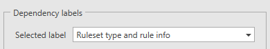
The Dependency Labels group on the Dependencies screen lets you quickly annotate your loaded dependency data, offering the following options:
-
Ruleset type – Display the type of rule set as a label. As with all of these auto-labels, the midpoint of the activity string is labelled, for example:
-
Rule info – Show the name of the rule and the rule index, for example, "02_LEVEL | Rule #4".
-
Ruleset type and rule info – show both of the above.
Choose your labelling option via the Selected label menu:
Note: You specify the type of dependency by your selection of tab on the Edit Dependency Rules screen.
Using Templates
If dependency data is loaded into the 3D view, it can be useful to use 3D view formatting to make things easier to interpret. For example, increasing or decreasing the size of activity points, or changing the colours of other screen items.
If you want your current formatting to become the standard for subsequent dependency visualization (for the current project), use Save Templates to store 3D display template information for each loaded overlay. You can then load these templates in future project sessions to reinstate the formatting you set up beforehand.
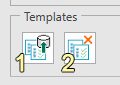
-
Store the current 3D window formatting as 3D view templates, for later reinstatement.
-
Load the 3D view templates associated with the current project and update the dependency data in the 3D window.
Dependency Processing
Clicking Go initiates sequencing: every activity point within your project data will be added to a sequence of events (if possible) based on how it relates to other activity points. In other words, the schedule is created and made ready for final processing in .
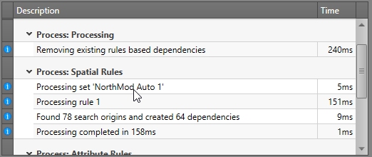
An example of messaging during dependency processing
During processing, information is created that can be optionally displayed (using the Show output check box, disabled by default). This information is in one of three categories:
- Errors: one or more activity points cannot be scheduled without violating base constraints. A sensible schedule cannot be created due to one or more issues.
- Warnings: things that, whilst they don't prevent a sequence from being generated, may need your attention.
- Messages: progress messages. These appear throughout processing and generally indicate status of each phase of processing.
During the processing of dependency rules, if any alerts are raised (for example, a rule gave rise to 0 dependencies), you will need to review the corresponding rule in the Edit Dependency Rules panel. The output message window will reference a rule index to make it easier to determine which item needs attention.
Dependency Loop Checking
A dependency can result in infinite scheduling. This can be as simple as activity 1 being linked to activity 2 and activity 2 being linked to activity 1, or it can be a more complex arrangement where an activity in the schedule links to another activity that will link through a chain of activities back to itself.
Warning: You cannot import schedule information to if dependency loops exist. They must be resolved before data can be exported.
Dependency loops are rarely a good thing so they are described, per instance, at the bottom of the Dependencies panel.
Once your dependencies have been checked (as part of dependency calculation), any recursive dependencies are shown in the list, plus the number of activities they may effect. In the example above, a simple 1-2-1 recursive link, only one activity is affected. The example shown at the start of this section would report a higher activity count (actually 40).
Note: You cannot create (or display an animation of) a schedule if dependency loops exist - they must be resolved beforehand.
Resolving loops can be achieved by either editing your dependency rules or using the manual editing tools to reverse or delete conflicting dependencies.
The list is interactive: click an entry to automatically zoom to the offending dependency - which makes it easier to resolve each of the issues before generating a final sequence.
- When you select a dependency loop from the list the data is filtered accordingly to show the relevant data only
- When you have resolved or removed the loop you can save the change and re-run the check. This will automatically clear any applied view filters.
You can also apply a global filter to the view of dependencies using the Filter list at the top of the View group, selecting from any of the currently defined filters (User, Design Type, Design Definition or Group Position).
Tip: Select the Invalid Dependencies Filter to display troublesome dependency strings for you to correct.
You can Save your task to remove any filters previously applied by loop detection routines.
Animate a Schedule
You can calculate your schedule (your sequence of activities) based on the currently defined activity points and dependencies.
If you have made any manual adjustments to your dependencies or
dependency rules, you must recalculate your schedule to ensure the
latest changes have been considered. This is done using Calculate the Schedule at
the bottom of the form: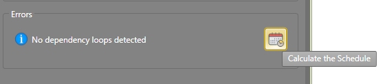
Providing there are no dependency loops (see above), you can do this at any time.
Once calculated, the Sequence control bar can be used to play back your animation (or use the slider bar to move through the time periods interactively).
The Sequence control bar allows
you to define the animation frames to be displayed at any one time,
the speed of playback, the direction of playback and other useful
parameters. Make the relevant settings on the control bar and click
Play: