
Stope Reconciliation - Input Settings
To access this screen:
-
Stope Reconciliation ribbon >> Input Settings.
This panel is used to set up a reconciliation scenario, or access an existing one for editing. You then detail the inputs for each reconciliation scenario.
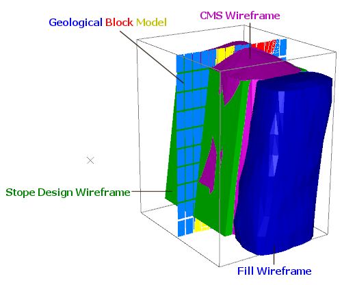
A wireframe representing your planned stope dimensions must exist. This is the Stope Design Wireframe and is compared to the latest field data, commonly a wireframe formed from a point cloud from a Cavity Monitoring System.
Optionally, you can enter other wireframes that represent filled voids around the CMS wireframe. These Fill Wireframes are attributed with a Fill Code and Fill Density.
An input geological model is optional, but if specified, can be used to calculate grades. The model fields that are reported are chosen at the bottom of the screen.
Access other stope reconciliation scenarios using the list on the left. See Stope Reconciliation.
Activity steps:
-
Display the Stope Reconciliation screen.
-
Choose your stope Reconciliation Method. See Stope Reconciliation.
-
Choose Wireframe Block Filling to use the model depletion method. This may not be suitable for narrow vein or vein-like deposits.
-
Choose Wireframe Boolean to evaluate against a modified evaluation wireframe formed by development shape removal with boolean operations.
-
-
Specify the Stope Design Wireframe representing the stope design. This is compared with the Stope Survey Wireframe (see below) to assess overbreak and underbreak.
Tip: output wireframes from Mineable Shape Optimizer (MSO) are an ideal input for the Stope Reconciliation tool.
-
Specify the Stope Survey Wireframe.
This is reconciled with the selected Stope Design Wireframe (see above).
Note: the Stope Survey Wireframe and Stope Design Wireframe must be different.
-
If available, specify one or more Fill Wireframes that represent filled voids around the scan data.
-
Click "+" to browse for a project file (you can edit the file afterwards if you need to).
-
In the Name field, browse for a fill wireframe.
-
Enter a Fill Code.
-
Enter the Fill Density.
-
-
Specify a Block Model to calculate associated underbreak and overbreak grades.
Once a model has been specified, define the following settings:
-
Density Field Name. Pick from any numeric field in the model.
-
Default Density of the model. This is used in the absence of density values in the model.
-
Block Model Fields from the list of numeric fields listed below. Check Should Report for each attribute that is to appear in the reconciliation results table.
-
You can sub-cell your model to provide more accurate boundary grade calculations (at the cost of performance) using Parent Cell Divisors. Click the browse button to display the Edit Parent Cell Divisors screen. This option is only available if you are using the Wireframe Block Filling Reconciliation Method (see above).
-
-
Decide if an additional Area wireframe is used, encompassing the Stope Design and CMS wireframe objects and designating zones by which overbreak and underbreak are reported (say, by hangingwall and footwall, for example):
-
Check Use Area Wireframe?
-
Define the Area Wireframe Method. This can be:
-
Custom – Specify an input Wireframe and Area Column that represents the solids that define areas for independent reconciliation.
-
Automatic – Automatically isolate areas in a wireframe through the presence of key structures, such as hangingwall and footwall, based on a nominated Alignment Source. This can be:
-
Axes – Deduce distinct stope reconciliation areas based on the alignment of data in relation to the world axes.
-
Fixed – Enter the Azimuth (running from footwall to hangingwall of the stope) and Inclination (angle from vertical) of the stope.
-
From File – Select an Azimuth Field Name and Inclination Field Name in the input solids to determine the alignment used for zone detection.
-
-
Note: If Use Area Wireframe? is unchecked, reconciliation results are not categorized by sub-area.
-
-
Optionally, specify Development Wireframes, typically output from Studio UG's planning workflow. If there were existing voids next to the stope, for example, in the case of an adjacent stope not being back-filled, the void stope CMS should be included in this section.
Note: If no development level wireframes are defined, reconciliation is performed between design and ground data without removal of development wireframes.
To add a development wireframe to your reconciliation case:
- Add (+) a development wireframe triangle file to the list.
- Continue to add wireframes until all potentially depleting development shapes are captured.
-
Run your reconciliation scenario, or batch of scenarios.
Related topics and activities