
Edit Shapes
To access this screen:
-
On the Apply Design Definitions panel, click the Edit Shapes button.
-
Display the Project Settings toolbar and select Edit Shapes.
This screen is used to define profiles that will be extruded along an FXS design string to create FXS solids for scheduling.
You can either choose from standard shapes and edit their dimensions, or you can define a free-form shape by defining a series of coordinates (known as a "point list" shape).
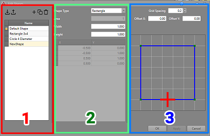
As with other screens, each item (representing a single FXS profile) is listed on the left of the screen. You can import and export profiles (useful for importing a standard set of operationally-approved shapes) and can add, copy and remove profiles using the tools shown in section (1), above.
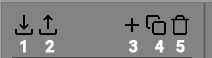
- Import profile data
- Export existing profile data (whatever is listed below)
- Add a new shape
- Copy the existing shape to a new item
- Delete the current shape
The middle section of the screen (2) contains the shape parameters. This will either be a set of editable standard dimensions (depending on the shape you choose) or a list of points (for free-form shapes) that can be set manually or interactively.
On the left of the screen is the shape preview (3). This displays a preview of the profile shape and, if a custom "point list" shape is being defined, can be used to interactively reposition profile points and change the resolution of the snapping grid (more on this below).
Note: This screen includes table grids that support multiple row selection.
Create a New Standard Shape Profile
In the following example, an arch shape is defined, although the principle is very similar for other standard shapes (anything other than [Point List]):
- On the left of the Edit Shapes screen, click "+" to add a new profile shape to the list below.
- Rename from the default value to something appropriate, e.g. "Arch 5 x 4"
- In the middle of the screen, select Arch from the Shape Type drop-down list.
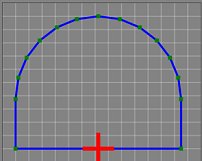
- A default arch profile is drawn in the preview window, and default values are shown for editing.
- Edit the Width to required drive width, e.g. "5"
- Similarly, edit the Height, e.g. to "4"
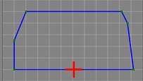
- Decide on the radius of the upper corners, e.g. "2.5"
(as this is half the width, this makes the roof hemispherical), for example:
-
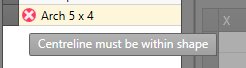
On the right of the screen, adjust the 'activity point', represented by a red cross. This is the point at which your FXS design string will be intersect the profile during extrusion. Adjustment is done by editing the Offset X and Offset Y values (see the following activity for an example).
The activity point must lie within the profile shape. If outside, a warning is shown next to the profile description in the list on the left, for example:
- Click OK to store the profile details and make the new shape selectable on the Design Definitions screen.
Create an Offset Anchor Point with Intersecting Wall
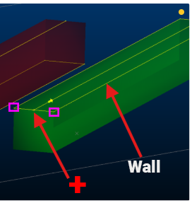
In this example, the FXS string represents the location of the top surface of the development profile (rectangular in this case), where the wall lies in the same plane, like this:
- On the left of the Edit Shapes screen, click "+" to add a new profile shape to the list below.
- Rename from the default value to something appropriate, e.g. "Rectangle 5 x 5"
- In the middle of the screen, select Rectangle from the Shape Type list.
- Enter a Width and Height of "5".
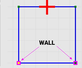
- On the right of the screen, enter "5" for Offset Y. This places the red + (the intersection point of the FXS string) at the top centre of the profile.
-
The purpose of the green and pink corner indicators becomes important at this point. The green points represent a profile corner (there are actually four of them but two are partly obscured). The pink indicators represent the wall intersection points. By default, they are at the bottom:
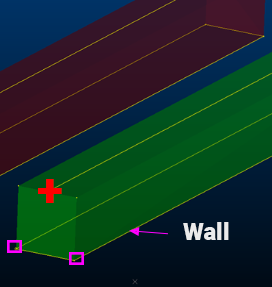
This would generate a solid like this:
However, this example requires the wall to be aligned with the FXS intersection point, so a little more preparation is required.
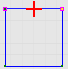
To finish the job, double click in both top corners to move the pink indicators to the top of the profile, as shown below:
- Click OK to store the profile details and make the new shape selectable on the Design Definitions screen.
Create a New Custom Profile Using the Editor
If you need a profile shape that doesn't match one of the standard types, you can create a custom 'point list' shape:
- On the left of the Edit Shapes screen, click "+" to add a new profile shape to the list below.
- Rename from the default value to something appropriate, e.g. "Arch 5 x 4"
- In the middle of the screen, select Point List from the Shape Type drop-down list.
-
Instead of displaying editable dimension attributes, a list of XY coordinates is displayed instead.
The list of points is an editable version of whichever standard previous shape was selected. So, you can edit a standard shape by selecting it (and editing dimensions if need be) then selecting the [Point List] type to make a modification to one or more shape vertices.
- You can edit any displayed point by manually changing the XY coordinates, or by dragging-dropping a point on the preview to a new position.
- Insert Point and Remove Point can be used to increase or decrease the complexity of the profile. At least 3 points must remain on the profile, so Remove Point is disabled if only 3 points are displayed.
- Click OK to store the profile details and make the new shape selectable on the Design Definitions screen.
Create a New Custom Profile Using A Digitized String
If the Point List shape type is selected, you can use the XY coordinates of a loaded (and displayed) closed string. Only closed strings can be picked and must be on an orthogonal plane. If a selected string is closed, or the selected trace is not on an orthogonal plane, the picking mode will be cancelled.
- On the left of the Edit Shapes screen, click "+" to add a new profile shape to the list below.
- In the middle of the screen, select Point List from the Shape Type drop-down list.
- Select Pick and left-click on a closed, orthogonal string in the 3D window. This will transfer the coordinates of the picked string to the shape editor table.
- You can edit any displayed point by manually changing the XY coordinates, or by dragging-dropping a point on the preview to a new position.
- Insert Point and Remove Point can be used to increase or decrease the complexity of the profile. At least 3 points must remain on the profile, so Remove Point is disabled if only 3 points are displayed.
- Click OK to store the profile details and make the new shape selectable on the Design Definitions screen.
Related topics and activities