
Edit Design Definitions
To access this screen:
-
Planning ribbon >> Preparation.
-
Select the Apply Definitions tab.
-
Click Edit Design Definitions.
Tip: You can also use the Project Settings toolbar to select Edit Design Definitions.
Define the design information used to generate your schedule-ready data for each of the design types supported by your product.
Design definitions determine how your schedule will be created. Each definition aims to accommodate operational constraints and other design decisions made by your organization, and these parameters can have a significant impact on how an optimal schedule is solved for your project's design files.
Each definition will determine things like how solids will be processed from the original data, for example the way data is segmented to form independent activities for scheduling, the size and shape of a fixed cross section, scheduling constraints and the rate of mining expected for each design element. For outline strings, the method and direction of extrusion is specified. Complex solids and wireframes are also defined, but require a smaller set of parameters as the transition to a solid is a relatively straightforward one with fewer variables than for fixed cross section and outline starting points.
You can apply the current set of definitions to your data using the Apply button (which will automatically update the Apply Design Definitions screen if it is displayed).
To apply the definitions and close the Edit Design Definitions panel, click OK.
Tip: Display the Edit Design Definitions panel
at the same time as the Apply
Design Definitions and other panels. Changes made to the
definitions are instantly reflected in the Apply
Design Definitions panel when definition changes are committed.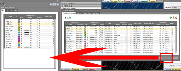
Note: This screen includes table grids that support multiple row selection.
Matching Attributes
In versions prior to version 2.1, Studio UG matched designs to definitions by the field DESIGNDF (the design definition Name). In these versions, you had to ensure you applied the design definition to your designs. Applying a design definition to a design would set the values of the DESIGNDF, COLOUR, LSTYLE, and SYMBOL columns. During processing, the design definition of a design was only matched by reading the values in the DESIGNDF column. This could lead to a mismatch between the value of DESIGNDF and the display Properties (COLOUR, LSTYLE, SYMBOL) if you modified the display properties of your designs without using the Apply Design Definitions feature. In effect, there was a risk of data duplication that could get out of sync.
In Studio UG version 2.1 and later designs are once again matched to design definitions by matching attribute values. This means that if the attribute values are on the design, you don't need to apply the design definition as it will automatically be matched during processing. The action of applying a design definition sets the matching attribute values on the designs so that the automatic matching will work. This provides more flexibility and can save significant amounts of time. If the designs already have the appropriate attribute values, you can jump straight to processing. To apply values to the matching attributes, you can use the Apply Design Definitions screen, standard Studio commands, or even use a script.
You can select one or more attribute definitions to use for matching. Each design definition must have a unique combination of values for the matching attributes. The matching attribute definitions are defined per design type. You can still match using the display properties (LSTYLE, COLOUR, SYMBOL), but you are no longer restricted to doing so. Matching on fields other than the display properties allows you to use the same design definition for designs that have different colours, for example. Activity Solids get their colour from their associated design, whether COLOUR is used in the attribute matching or not.
In a way this is how Studio 5D Planner worked: it was just hard-coded to match by the attributes COLOUR, LSTYLE, and SYMBOL. In Studio UG, this restriction is lifted.
Each design type must match on at least one attribute. You can choose to match on the system attributes COLOUR, LSTYLE, and SYMBOL or any of the user attributes. The design definition needs a unique name as well.
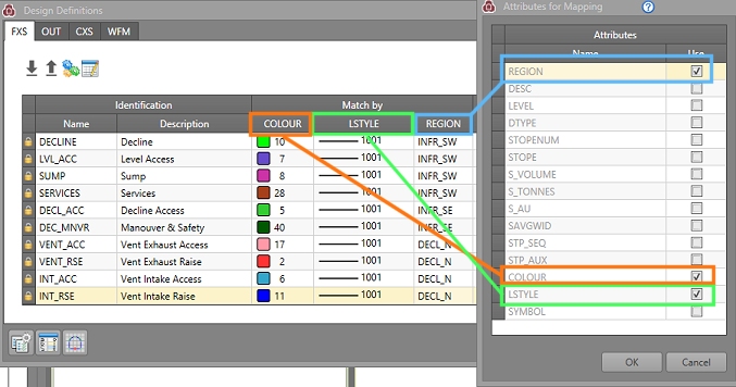
These "Match By" attributes are configured using the Attributes for Mapping panel, a simple field chooser that updates (and is synchronized with) the Edit Design Definitions table.
If it is not possible to create unique combinations of matching attributes for existing definitions, non-unique value combinations will be highlighted in the definitions table, for example:
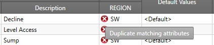
The Solid colour will be taken from the design file, regardless of whether COLOUR is used in the attribute matching or not.
How Mapping Attributes are used in Generating Definitions
The Generate Design Definitions function is a useful tool that allows you to extract information from external files and use it to construct design definitions automatically.
This panel also honours the current mapping attributes to automatically extract definitions from the selected file. For example, if your mapping attributes are LSTYLE, COLOUR and SYMBOL, the Generate Design Definitions panel will automatically construct definitions based on all combinations of values found for these attributes in the file.
See Mapping Attributes.
See Generating Design Definitions.
Creating Design Definitions
Definitions can either be assembled manually, or by generating them from existing file data (or a combination of these methods).
The parameters available for each design type are described in the help topics for each design type (see below, or Related Topics for more information).
Definitions can be created anew if you wish, using the green + icon at the top right of the panel. This allows you to define a design element from scratch. You can also choose to copy an existing definition, which can be useful to retain standard settings.
Copy definition:
Deleting Design Definitions
A design definition can be deleted providing it has not already been used to create an activity (i.e. the design definition has not been subject to processing yet). If it has, the definition is locked to ensure subsequent processing can continue following design changes. Otherwise, the currently selected definition can be deleted using the red x icon at the top right of the panel.
Using the Definitions Table
The definitions table for each design type is context-sensitive: not all parameters may be available, depending on other values set for the current definition. For example, the Segmenting - Number cell will only become available if the segmenting method is [by Number]. Each of the available parameters is explained in the focussed help topic for each design type.
Transferring Definitions
You can import and export your design definitions for use in another project, or as a safety net to reinstate previous settings.
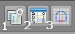
Use the Design Definitions panel to edit or construct definitions manually, or Import them in from an external settings file (1), or Generate them from an existing Datamine table (3).
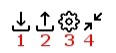
You can also Export your current settings for later use (2). To set up attribute matching, use Edit Matching Attributes (4)
Design Type Support
The parameters available for each design type are different. For more information on setting up a particular design type, see below:
- Edit Design Definitions - FXS
- Edit Design Definitions - Outlines
- Edit Design Definitions - Complex Solids
- Edit Design Definitions -
Wireframes
Other Functions
You can also access these supporting functions from this panel, using the buttons in the bottom left corner:
-
Edit Attributes: access Studio UG's Edit Attributes panel.
See Edit Attributes.
-
Edit Default Values: set up default values for a block model.
See Edit Default Values.
-
Edit FXS Shapes: define your FXS profile shapes here.
See Edit FXS Shapes.
Related topics and activities