|
|
Studio UG Tutorial - Design Definitions Configuring the |
Underground Planning Tutorial - Design Definitions
Design definitions determine how your design data will be prepared for scheduling and the rate of mining for each structure type.
-
In the case of fixed cross-sectional (FXS) data, a design definition includes defining the profile/shape that will be used to extrude along the string and create a solid that can be segmented, then each segment sequenced and evaluated. Your project consist of four FXS design file covering decline, level, ore development and ventilation development.
-
In the case of wireframe design data (your project includes a wireframe representing the mineable stopes), the design definition will describe the rate at which the wireframe volume will be extracted.
Your project will be supported by a total of fifteen separate definitions, each of which corresponds to a particular structure within your design data. Most relate to fixed cross-sectional data.
In the following exercises, you will define one of the FXS shapes (the one used to extrude along the main decline structure) and then define the display settings, segmentation, scheduling constraint and rate of mining for that structure. The remaining design definitions will be loaded from the provided XML file.
Design definitions require a unique combination of "Matching Attributes" (you can find out more about this here) but for this tutorial, only the COLOUR attribute - the only matching attribute - and the definition name are required to be unique for each definition. In other words, you won't be changing the default matching attribute configuration (where COLOUR is the only matching attribute) in this exercise.
You will also create a design definition for your stope volume wireframe. The activities that spawn from this definition will be used later to trigger another activity: backfilling. This is an example of a 'derived activity'.
Prerequisites
-
You have completed the previous section (Assign Attributes)
Exercises in this section
This section contains the following exercises:
- Access the Design Definitions Panel
- Create the Decline Definition
- Define and Assign the Decline FXS Shape
- Set up the Wireframe Design Definition
- Load the Remaining FXS Definitions
- Assign the Decline Design Definition
Exercise 1: Access the Design Definitions Panel
- Following on from the previous exercise, using
the Planning ribbon,
select Definitions (if
required, click Show
first).
This displays the Apply Design Definitions panel. There aren't any definitions for your project yet, so the table shows only one entry - the default item representing an absent definition.
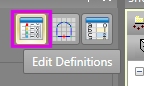
You'll come back to this screen once you have defined your decline design definition and loaded the remainder from XML. You will then interactively apply it to the main decline string as an example. - To start creating and editing design definitions,
click Edit Definitions:
- The Design Definitions panel is displayed. This panel segregates definitions by data type. As your project includes only FXS and wireframe data, you'll be using those tabs only.
Exercise 2: Create the Decline Definition
In the following exercise, you will define the display settings for the decline string. You will also split it up into segments, each of which will become host for an activity point. Finally, you'll set up the mining rate and scheduling constraint for the decline activities.
- In the Design
Definitions panel, Click "+" to add a new row
to the definitions table.
A definition called "New" is added with default values. - Double-click inside the Name field and edit it to "DECLINE".
- Similarly, edit the Description field to read "Decline".
- You're going to show the decline as a bright
green design string (the resulting solid will also be green),
so click inside the COLOUR field
and select the [10] item (bright green). COLOUR is the only matching
attribute for your project, so sits below the Match
by group (this can contain one more attributes in other
projects).
")
Studio UG uses a concept of "matching attributes" to differentiate unique design definitions. You can choose any attribute or group of attributes (in which case it is the combination of attribute values that represent each distinct definition).
In addition to a unique Name, you can choose the attributes that represent your definition using the Attributes for Mapping dialog. In this example, the default setting is used; only COLOUR is used to segregate each definition. This means that every COLOUR value in your definitions table must be unique. Design data that is added to the project will be automatically matched against the COLOUR attribute value during processing. Where a match is found, the corresponding design definition is automatically applied.
- Ignore Shape for now - you'll define a cross-sectional shape for the decline FXS string in the next exercise.
- You're going to split your decline up into 12m intervals; in the Segmenting - Method cell, select the [By Length] option.
- You are prompted to enter a Length.
In this case, enter "12".
Studio UG also lets you define a number of segments using the [By Number] option, and works out the distance for you. For this example, though, the length is important as 12m represents a pragmatic way to break up the decline string into schedule-ready solids.
- Default Values aren't important for this definition so can be left as is.
- The default constraint is fine too; you want the decline development to start as soon as the completion of precursor activities is complete. This becomes clearer when you set up dependencies later on.
- The equipment assigned to the project has been determined to progress the decline at 100 meters per month. As such, in the Quantity field, enter "100", select [m] from the Unit drop-down list and select [Month] from the Period drop down list.
- Check your design definition matches the properties
listed below:
Name: DECLINE
Description: Decline
Colour: 10
Linestyle: 1001
Symbol: 201
Shape: Default Shape (will be changed in the next exercise)
Method: By Length
Length: 12
Default Values: <Default>
Default Constraint: As Soon As Possible
Quantity: 100
Unit: m
Period: Month
Exclude: disabled
Exercise 3: Define and Assign the Decline FXS Shape
For your project, the decline will be excavated using an arch-shaped profile. The arch will be 4.5 meters wide by 4 meters tall. In this exercise you will define this profile shape, including how the FXS string relates to it positionally (i.e. the position at which the profile shape is applied to the string).
Other shapes will be used in your project, but they will be imported from XML as part of this exercise.
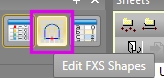
- Leave the Design
Definitions panel open (although you may need to move it
out of the way) and click the Edit FXS Shapes button on the Apply
Design Definitions panel:
Studio UG will generally let you open any number of panels at once, with each panel being aware of changes being made in other areas. This is a really useful way to set up multi-faceted design descriptions without have to close and reopen panels unnecessarily.
- The Edit Shapes
panel shows the default square profile, i.e.:
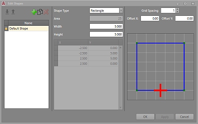
- You're going to define a new shape for your decline arch. Click the "+" button to add a new entry to the listing on the left: "NewShape".
- Edit this description to read "Arch 4.5x4".
- Select [Arch] from the Shape Type drop-down
list. The default Arch profile appears:
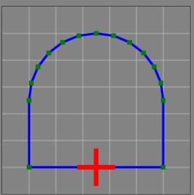
- Enter "4.5" into the Width field.
- Enter "4" into the Height field
- Enter "1.75 into the Arch Radius field.
- In the Grid Spacing field (above the arch preview), enter 0.8.
- The red cross indicates the point at which the FXS string will intercept the profile during extrusion. For this tutorial, the base-centre position is fine.
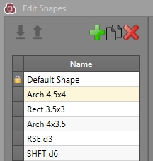
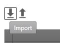
- Now, you can import the remaining 4 shapes
required for the other design definitions, using the Import
button:

- Browse to your project's "XML" sub-folder
and load the file "FXSShapes.xml". This loads the remaining
definitions - select each one to see the differing configurations:
- Click OK to dismiss the Edit Shapes panel.
- Back in the Design Definitions panel, select the Shape field for your DECLINE design definition and select [Arch 4.5x4].
Exercise 4: Set up the Wireframe Design Definition
Your planning project includes the excavation and backfilling of stopes. The initial excavation planning constraint and rate of mining is determined by the design definition that you will create in the next exercise.
- In the Design Definitions panel, select the Wireframe tab.
- Click "+" to add a default wireframe design definition entry.
- Edit the table row so that it matches the following
properties:
Name: STOPE
Description: STOPE
Colour: 37
Linestyle: 1001
Symbol: 201
Default Values: <Default>
Default Constraint: As Soon As Possible
Quantity: 45000
Unit:miT
Period: Month
Exclude: DisabledSegmentation and shape definition is not relevant for wireframe design data.
- Select the Fixed
Cross Sectionals tab.
Exercise 5: Load the Remaining FXS Design Definitions
The remaining definitions for your project are held in an external XML file.
- Swap to the Fixed Cross Sectionals tab.
- In the Design
Definitions panel (Fixed Cross Sectionals tab), select
Import:
- Browse to and open the file "DesignDefinitions.xml" from your project folder's "XML" sub-folder.
- After a few seconds, the remaining definitions
will appear in the table:
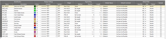
- Click OK to return to the Apply Design Definitions panel.
Exercise 6: Assign the Decline Design Definition
Your tutorial data is already set up with most of its design definitions. The only missing element is for the main decline drive, which you'll add now. The definition used will be the one you created manually in the previous exercise.
- To assign design definitions to data, you need
to load the data.
Click Load Designs:
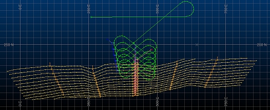
- Your fixed cross-section design data is loaded
(the type of data that is loaded will depend on the selected table
tab, in this case, FXS):
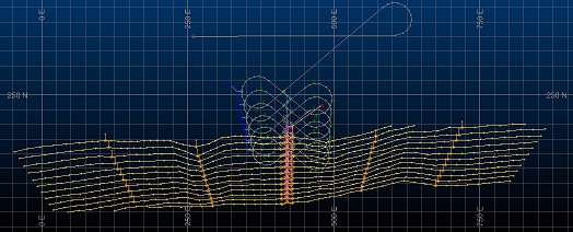
- The grey decline string at the top of the image
above doesn't currently have a design definition. This means that
it cannot be used to generate solids data and segment it into
activities for scheduling.
Left-click the decline string in the 3D window to select it: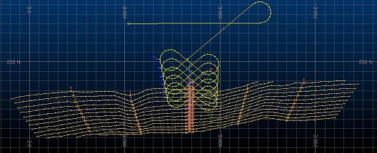
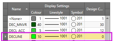
- In the FXS
table, select the DECLINE table row to highlight it:
- Click Apply
to Selected and click away to see your decline string coloured
in green. This means the definition has been successfully applied:
- Enable Filter using selected definition - this lets you see the DECLINE structure on its own in the 3D window.
- Cycle through the other table entries (click
each one) to show the structures in isolation:
The view will automatically zoom to accommodate the selected item data as Zoom all when filter changes is enabled. - Disable the Filter using selected definition check box and select the WFM tab.
- Your imported wireframe stope data is
displayed:
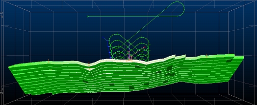
Your loaded wireframe data has already been associated with the definition you created earlier (which is why it is shown in green) so nothing more to do here. - Click Save Designs to commit the latest definitions to your design data.
- Unload your design data using the Unload
Designs button:
Your design definitions are now set up ready for validation.
