|
|
Studio UG Tutorial - Validation Validating your design data before processing |
Underground Planning Tutorial - Data Validation
It's always a good idea to review your design data before you subject it to processing. This is to ensure that the solids that are generated accurately represent the mining activities you wish to schedule and removes the possibility of non-mineable sequences.
At this stage, you have 'connected' your design definitions to your design data so Studio UG can construct the relevant activity points for your underground plan. You haven't set up any specific dependencies yet, but that comes later. For now, you need to verify that your design data doesn't include geometry that cannot be mined, considering your current operational constraints. In some cases, validation will detect more fundamental problems such as duplicate strings or points that could give rise to multiple concurrent activities of the same type - this is rarely desired.
Validation can also prepare your data where discrepancies occur, such as automatically closing string data defined as the Outlines or Complex Solids design type. It also provides useful proximity checks to ensure inter-level spacing is adequate for the rock type and so on.
In the following exercise, you're going to validate your project with the default settings, then review the results and understand them. Folowing that, you're going to relax one of the validation rules slightly for fixed cross sections in order to let validation complete without errors.
Prerequisites
-
You have completed the previous section (Configure Design Definitions)
Exercises in this section
This section contains the following exercises:
Exercise 1: Validate with Default Settings
- Following on from the previous section, activate the Planning ribbon and select Validation.
- The Process
Validation panel is displayed.
Click Go to start the validation of your design data with the default settings. The default settings are essentially "check everything on everything". The checks that are made are explained in more detail in your context-sensitive Help files, but in essence they are grouped into settings for each design type.
Your fixed cross-sectional data will be validated to make sure:
- Strings are opened if they are closed (it's uncommon to extrude a profile shape in a closed boundary, although it is possible)
- String segments that change azimuth by more than 90 degrees are reported (tighter corners than this aren't desired for this project)
- Strings can't dip by more than 15 degree changes between line segments - this is limited by your machinery capabilities
- Horizontal design strings can't deviate by more than 9.46 degrees from horizontal
- Vertical design strings can't deviate by more than 60 degrees from vertical
- There are no string cross overs in the same plane (i.e. no coincident string data)
- There is a minimum vertical separate of 10m between strings (this is likely to be governed by machinery and the material being mined) - Process can take up to a couple of minutes
to complete. Once complete, a report is displayed. This report
lists all data that fails one or more of the validation rules.
In your case, the Fixed Cross Sectional data has one or more issues
to deal with:
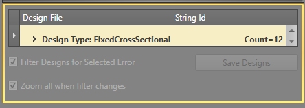
As displayed, there are 12 items (Count=12) of design data that have failed validation and need to be reviewed. - Expand the Design
Type: FixedCrossSectional list to display the error conditions
that have occurred.
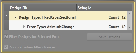
- In this case, one or more design strings show a change in azimuth (between subsequent segments) that exceeds the predefined limit (the default value, and the one used here, is 90 degrees).
- Expand the Error
Type: Azimuth Change list to show the 12 string entities
that exhibit this validation failure:
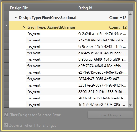
- Select the first "fxs_vent" item in the list and enable both Filter Designs for Selected Error and Zoom all when filter changes check boxes.
- Zoom out slightly with the middle mouse wheel
(or use the View ribbon's zoom functions to do the same). The
resulting string is one of the vent raise strings for the exhaust
infrastructure:

- Although it's hardly noticeable, the two string segments violate the Maximum Azimuth Change validation rule (coincident edges cannot vary by more than 90 degrees) by a very small amount.
- Select some of the other "fxs_vent" entries in the table - the result is identical; they all suffer from the same failure.
- Resolution in this case would be to either adjust each of the strings to make the angle between segments less acute or to relax the validation rule. In this case, you're going to do the latter.
- In the Validation Options area (expand it), change the Maximum Azimuth Change value to "95" and click Go again to revalidate your data.
- This time, there are no validation errors, so you can proceed to solids generation.
