|
|
Studio UG Tutorial - Process Solids Processing your input data into schedule-ready solids |
Underground Planning Tutorial - Process Solids
Studio UG uses your input design data (fixed cross-sectional strings, outline strings, complex solid strings and imported wireframes) as a starting point for creating solid volumes that can be assigned an 3D activity point within your schedule.
In the case of string data (FXS, CXS, Outlines), volume data is generated by extruding from a base string,or between strings, to form closed volumes for evaluation and segmenting. Wireframe data is not segmented but is instead depleted according to the specified mining rate of the design definition.
Solids creation, referred to in Studio UG with the general term of "Processing", brings together your design data, definitions and other project settings to create a series of solids, containing one or more activity points that can be scheduled, potentially with other dependencies injected into the mix (dependencies are covered in a later section).
In the following series of exercises, you will process your design data (four FXS designs and one wireframe) into solids and activity points. You'll also set up a derived activity (backfilling) that will apply to all wireframe data scheduling e.g.:
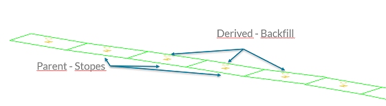
In this scenario, wireframes will be generated from the derived activity definition.
Prerequisites
-
You have completed the previous section (Validate Design Data).
Exercises in this section
This section contains the following exercises:
Exercise 1: Define Backfilling Derived Activity
- Activate the Planning ribbon and select Process.
- The Processing panel is displayed. The majority of the panel is comprised of empty progress bars (these fill up during processing) with the lower section dedicated to showing the results of processing as either errors, warnings or messages.
- Studio UG
uses derived activities to to represent the different activities
happening on a specific task. In your project, backfilling is
a derived activity and will have its own rate for the evaluated
in situ stope (WFM) volume.
The in situ volume will
consider the total stope volume before the ore development depletion,
as the whole volume will be backfilled.
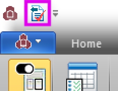
Click Setup Derived to display the Derived Activities panel: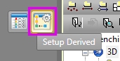
")
The Processing panel also provides instant access to the Apply Design Definitions panel.
- Click the "+" button (top right)
to add a new row to the Derived
Activities table.
Each derived activity is associated with an Assignment Filter and Expression (to determine how the resulting volume will be evaluated). This information is entered into the lower half of the screen. The lower table automatically appears when you create the first row in the table. For now, you'll continue to enter the derived activity definition and populate the lower table afterwards. - Edit both the Name and Description to read "BackFill".
- Backfilling relates to the entire in situ stope volume. The system wireframe filter is perfect for this assignment, so select [*WFM] from the Parent Filter drop-down list.
- Use the default [201] Symbol.
- You're going to offset your derived activities
slightly from the stope wireframes. This is handled by the Point Translation options.
Derived activity points will be created 1m higher than the parent
stope data, so choose [Z] as the Axis
and enter "1" for the Offset.
Within Studio UG it is not valid to have two points at exactly the same 3D position in space. It is therefore necessary to specify the translation of the newly created point using the Point Translation parameters, with respect to the original point. In addition to this the system also ensures that no points are coincident by adding an increment to coincident point elevations automatically. - You don't have to created derived activity
wireframes, but in this case select the Wireframes
- Create check box and
set a Colour of [18]
(pale red).
Your backfilling derived activity will progress at a specific daily rate. - Set up the following Duration
/ Rate fields:
Quantity: 610
Unit: im³
Period: Day - Backfilling needs to start as soon as the schedule permits it, so [As Soon As Possible] is the correct Constraint.
- Check that your Backfill
activity is defined as follows:
Name: BackFill
Description: BackFill
Parent Filter: *WFM
Symbol: 201 (default)
Point Translation - Axis: Z
Point Translation - Offset: 1
Wireframes - Create: Enabled
Wireframes - Colour: 18
Reverse: disabled
Activity Type: Fixed Rate
Quantity: 610
Unit: bfm³
Period: Day
Constraint: As Soon As Possible
Exclude: disabled - Next, you need to define a field name that will receive the calculated volume results. This is done using the lower table. Click the "+" button in the lower half of the screen.
- Select [Backfill_Volume] from the Field Name drop-down list.
- Select [*WFM] from the Assignment Filter drop-down list.
- You want to report the in
situ volume of backfill activities, so click inside the
Expression field, then
click the browse button to display the Expression
Builder panel:
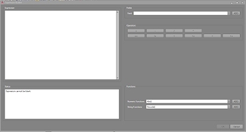
- In the Expression
field, enter "Insitu_Volume" (exactly as shown here,
without quotes). This is a system property that is available to
all Studio UG projects.
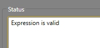
You'll know you've typed it correctly as the Status
field will show the following message:
- Click OK to return to the Derived Activities panel.
- Make sure your derived activity expression
details are as shown below:
Field Name: Backfill_Volume
Assignment Filter: *WFM
Expression: Insitu_Volume - Click OK to return to the Processing panel.
Exercise 2: Process Design Data
Now that you have set up your derived activity, you can process your design data, generate the derived activity volumes and see a report.
- Back in the Processing
panel, click Go.
Processing starts. The order of processing is always the same and reflected by the top-bottom order of progress bars. Each data type is processed in order, then the model is interrogated according to the interrogate rules you set up in a previous section (evaluation, depletion, then reevaluation in this scenario).
As your project doesn't contain complex solids or outline design strings, these steps are skipped.
Finally, derived activity volumes are generated and evaluated.
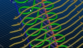
Your volumes are displayed in the 3D window as they are created, and the model section is displayed as depletion is performed:
FXS volumes: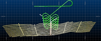
Wireframe (stopes):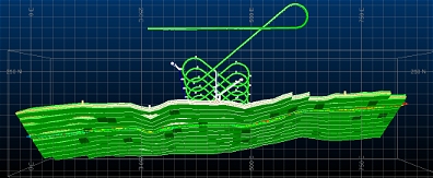
Block model interrogation and depletion: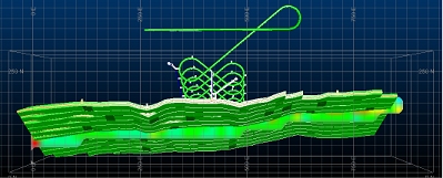
Derived activity (backfilling) volumes: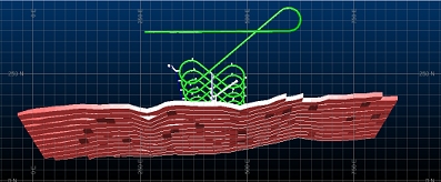
- The process takes a few minutes to complete
(geological interrogation is the lengthiest task).
The actual time taken is shown at the bottom of the Process output table in the Process: End Processing section e.g.: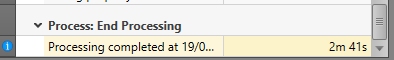
- The Process
output table can provide 3 different levels of information;
errors, warnings and messages. "Errors" will always
need to be reviewed and resolved before you continue, "Warnings"
are highlights showing where elements of your output are unusual
but could still be subject to scheduling and "Messages"
are status updates that indicate successful processing.
In your case, there are 35 messages and no errors or warnings. This indicates that your design data was processed into solids and activity segments/points without any problems.
Review the list of messages to better understand the steps Studio UG takes to process your tutorial design data. - Save
your project:
Disable all Auto Load and Save check boxes.
The next step is to set up some inter-activity dependencies. This is covered in the next section.
