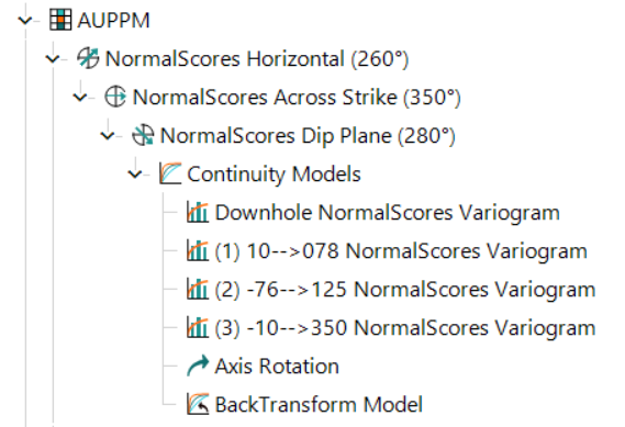
Model Variograms After Directional Continuity Analysis
After selecting the direction of greatest continuity and inserting Continuity Models, you can model the variograms in the direction you have selected. Continuity models are generally inserted beneath the dip plane variogram fan, but Supervisor allows you to insert them under any variogram fan (this may be useful, for example, if your deposit is flat or omnidirectional). Four variograms are automatically inserted with a continuity model: Hole direction, Direction 1, Direction 2 and Direction 3.
The hole direction variogram is calculated in the direction 00-->000 (initially), or as a downhole variogram if drillhole data was loaded. You can then subsequently set this to a direction that reflects the average orientation of the drilling (see Set the Downhole Direction).
The other three directions are calculated based on the directions identified in the three planes during Directional Continuity Analysis. When the continuity model is inserted below the Dip Plane variogram fan, as shown below, the variogram models represent the following:
- Direction 1 – Plunge (the direction of maximum continuity on the dip plane).
- Direction 2 – Minimum continuity on the dip plane.
- Direction 3 – Minimum continuity perpendicular to the dip plane.

Note: The Back Transform Model only displays if a normal score transformation has been applied to your data.
Where variogram models have been inserted under Horizontal or Across Strike variogram fans, the variogram models represent the following:
- Direction 1 – Direction of maximum continuity selected in that plane.
- Direction 2 – Direction orthogonal to Direction 1 on the plane.
- Direction 3 – Orthogonal to both Direction 1 and Direction 2.
Tip: In some cases, you may not be interested in all four directions for a given variogram. You can delete an individual model by selecting it an press the Delete key on your keyboard, or by right-clicking on the model, and selecting Component » Delete. Only the selected direction is removed.

