
Cross Continuity Models
Cross Continuity Models allow you to analyse the spatial correlation between pairs of assay types in a particular region of interest. To make a cross variogram you must have two different assay types loaded into Supervisor.
Cross Continuity Models can be inserted beneath any Data Loader Component or Domain component that has multiple child assay components. Cross Continuity Models can be inserted in two possible ways.
- Using the Cross Variogram component (recommended). See Insert a Cross Variogram Component.
- Using regular variograms and continuity models. See Insert a Cross Variogram Using Continuity Models.
Note: The results produced by each of the methods listed above will be the same. The method chosen is a matter of personal preference.
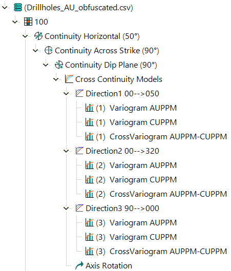
When a Cross Continuity Model is inserted, the following components are added.
- Continuity Horizontal variogram fan.
- Continuity Across-Strike variogram fan.
- Continuity Dip-Plane variogram fan.
- Cross Continuity Models component.
- Three Directional Variogram models containing all direct variograms and cross variograms for each assay and assay-combination.
- Rotation component.
The image below shows an example of the Project Tree after a Cross Variogram has been inserted under a domain with two child assays.
Each of the child variogram models can be fitted manually and honour the following Linear Model of Coregionalisation (LMC) restrictions.
- All models must have the same number and type of structure.
- For a single assay, all models must have the same sills for each structure.
- For a single direction, all models must have the same ranges for each structure.