
Insert a Cross Variogram Using Continuity Models
This topic describes how to insert Cross Variograms manually and configure variograms for the two assays that you want to compare. If you haven't used Cross Variograms in Supervisor previously, see the recommended way to Insert a Cross Variogram Component. The final results between the two processes are the same.
When modelling Cross Variograms, the model must be positive semi-definite for the bivariate case. This is a requirement for the estimation process. You must first select the univariate models from the assay Continuity Models.
Notes:
To create a cross variogram, you must group your data in Domain/Assay, where a domain has two sub-assays. See Group Data.
Continuity models need to be created for each assay to be used in the cross variogram.
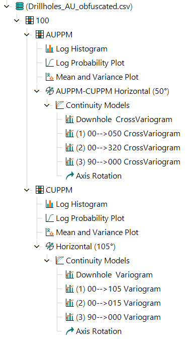
The image below shows an example of the Project Tree with the components required for a cross variogram. The assays, AUPPM and CUPPM, are grouped beneath the domain 100. Each assay has a Continuity Model component used to inform the AUPPM-CUPPM Horizontal variogram fan component and its subsequent Continuity Model component.
Activity Steps
- Configure your data so you have a domain with two sub-assays.
- For each assay:
- Insert and configure variogram fans. See Insert Variogram Fans.
- Insert and configure variogram models. See Insert Variogram Models.
- Insert the horizontal continuity fan beneath the domain.
- Right-click the domain in the Project Tree and select Add » Horizontal Continuity Fan from the menu.
- Specify the assays for the horizontal continuity fan.
- Select the horizontal continuity fan beneath the domain in the Project Tree.
- Select the Data tab in the Property Panel.
- Select the Assay and the Cross assay.
- Update the horizontal continuity fan component. See Update Components.
- Insert the continuity model beneath the horizontal continuity fan.
- Right-click the horizontal continuity fan beneath the domain and select Add » Continuity Models from the menu.
- For each continuity model:
- Select the Continuity Model component beneath the domain in the Project Tree.
- Select the Coregionalization tab in the Property Panel.
- Click the ellipsis (...) next to the Coregionalization Model field. The label of this field matches the assay chosen in step 4c.
The Models for Coregionalization window displays.
- Select the Continuity Models component.
- Click OK.
- Select any of the Cross Variogram components beneath the domain in the Project Tree to review.