Sections Tools
-
Click
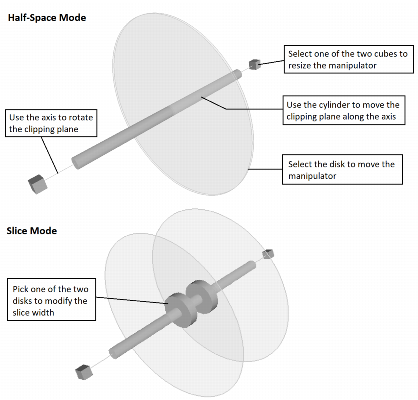
 to enable/disable the Clipping. This mode allows you to clip the scene along a plane. Half the space will be removed from the view of the plane. When activated, it opens the Plane definition. A slice clipping can also be achieved to manage two parallel clipping planes on both sides of the reference plane. Only the scene between two planes will be visible.
When
 to be able to translate, rotate and scale manipulator and the
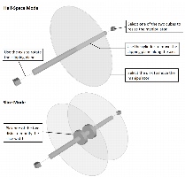
-
 Use the Knife to create a cross-section on the fly. Clicking this button will activate the cross-section definition mode. This mode is also reachable through the keyboard shortcut C. Simply draw a line on the 3D view to create the corresponding cross-section. The hatched side will be cut.
 Press Shift to invert the cut direction. To simplify the cross-section drawing, the orthographic view mode is automatically activated. Once the cross-section is created, click View from section (keyboard shortcut: L) to set the camera in front of the cross-section.
You can also press Ctrl during the outline to automatically set the camera in front of the cross-section. The +/- keys enable to go forward/backwards the cross-section.
Press Esc or
 to exit the Knife Mode without modifying the cross-section. Select/deselect Section to enable/disable the clipping of the scene. Cross-section parameters are then reachable and can be modified through the Plane parameters.
-
 Select the
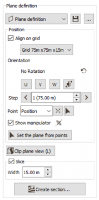
-
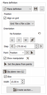
Plane definition: By default when digitalizing a clipping plane, this selector is initialized on ’New’. In this case, the plane definition is linked with the 3D parent scene.
Click
 to save the current plane. If the name entered to store the plane already exists, a confirmation message to overwrite it will pop up.
 Note: Storing a plane definition enables you to reload all the defined parameters in another 3D or section view. You will also be able to display the plane as a dedicated item / layer in the 3D Viewer / Map.
You can also initialize the plane definition from an already saved plane.
Click ... to open the Section definition dialog window.
Specify the current Position of the section plane (and manipulator):
- Select Align on grid to define the reference system according to the grid axes U, V, W (different from the main axes if the grid is rotated). Select which grid the system should refer to in the next list. This option is only available if the scene contains at least one grid item. If the option is not selected, the reference system will be defined according to the main axes OX, OY, OZ.
-
Define the Orientation of the section plane:
-
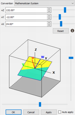
Click
 to open a Rotation window and define an orientation in the convention of your choice (mathematician, geologist,...).
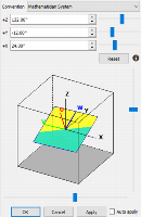
-
If alignment is made along the main axes, the rotation is defined according to the main axes X, Y, Z.
- Click X to set a vertical section plane perpendicular to the OX axis.
- Click Y to set a vertical section plane vertically perpendicular to the OY axis.
- Click Z to set an horizontal section plane perpendicular to the OZ axis.
- If alignment is made along the grid axes, the orientation is defined by the grid and is greyed-out (it cannot be customized).
- Click the button Reverse Plane Normal
 to reverse the section plane switch between clipping what is behind or clipping what is front of the clipping plane.
-
- The section plane may be moved backward and forward using the arrows

 with a given moving Step. + / - can also be used as shortcuts to navigate into sections. Enter a value in the Step box. When alignment is made along the grid axes, the step is defined by the grid resolution (i.e. the number of cells along U, V and W).
 -
Specify the Position of the section plane (and manipulator) by entering its coordinates:
- If alignment is made along the main axes, the section plane position will be defined by the X, Y, Z absolute coordinates. Enter a value for each coordinate in order to accurately tune the section plane position.
- If alignment is made along the grid axes, the section plane position will be defined by the grid indices IX, IY, IZ of the selected grid. Enter a value for each grid index in order to accurately tune the clipping plane position.
- Click
 to reset the position to the center of the scene (depending of the displayed objects).
 - Click to set the position from a picked point (associated with an object displayed in the scene). Pressing the Shift key when picking will define the exact position of the picked object. Otherwise, you will get back the coordinates associated with the picked object (the centroid of the cell if you pick a grid for example).
- Tick/untick the Show manipulator option to alternatively show/hide the manipulator.
- Click Clip plane view (keyboard shortcut: L) to set the camera in front of the cross-section. In Slice mode, as there is an ambiguity of the "front" position, you can use the button Reverse Plane Normal to reverse the camera position of the other side of the section plane.
- The section plane can also be defined passing through two points (with a vertical direction) or through three points to align the plane on those points. Click on Set the plane from points to pick points that will define each plane with the left button of the mouse. To end the picking phase, simply press the right button.
- Check the Slice option to manage two parallel clipping planes on both sides of the reference plane. Only the scene between the two planes will be visible. Enter a value in the Width box to specify the distance between the two clipping planes.
- Click Create section to open the Section view with all the items and properties already set.
-
-
 The Fence digit allows you to clip the scene along various consecutive panels, each fence panel being defined by two points, with a 2D rendering in a Section view. In Fence mode, the fence is added to the view but does not interact with the objects being displayed,.
Activate the option and pick the continuous sequence of points that will define each panel. Each point is digitized by picking with the left button of the mouse. To end the picking phase, simply press the right button. The various planes which compose the fence will be represented at the end of the digitalization in the 3D scene by green parallelepipeds. Picked points and other fence parameters are then reachable and can be modified through the Fence definition.
-
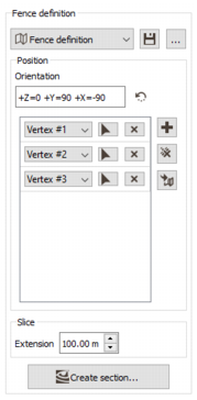
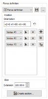
 Select the Fence definition to edit the fence parameters:
-
Fence definition: By default when digitalizing a fence, this selector is initialized on ’New’. In this case, the fence definition is linked with the 3D parent scene.
Click
to save the current fence. If the name entered to store the fence already exists, a confirmation message to overwrite it will pop up. Note: Storing a fence definition enables you to reload all the defined parameters in another 3D or section view. You will also be able to display the fence as a dedicated item / layer in the 3D Viewer / Map.
You can also initialize the fence definition from an already saved fence.
Click ... to open the Section definition dialog window.
Specify the Position and orientation of the section panels:
-
Click
to open a Rotation window and define an orientation in the convention of your choice (mathematician, geologist,...). The rotation defines the orientation of all pillars supporting all panels. The rotation is common to all planes of the fence. A vertical rotation is defined by default.
-
The following area is designed to handle fences (which consist of a continuous set of panels). Click
 to pick the continuous sequence of points that will define each fence panel. Each point is digitized by picking with the left button of the mouse. To end the picking phase, simply press the right button. The various panels which compose the fence are represented in the 3D scene by green parallelepipeds to check and visualize the picked points.
You can click again on the
button to add points. They will be added at the end of the existing sequence.The coordinates (and the Sample Number of the corresponding object) of each picked point are available by clicking on the corresponding Vertex widget. You can edit and modify them or use the
button to change of picking point.Click
 to delete the complete sequence of points or
  to remove each point individually.
Instead of being manually digitalized, fences can also be imported by clicking on
 Load fence path. Points which define the fences can be contained in a shapefile (.shp), in a CSV file (.csv) or in an Isatis.neo polyline file. Please go to the Load fence path section for more information.
 -
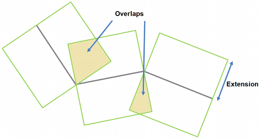
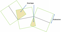
In the Slice section, enter a value in the Extension box to specify the distance around the fence to consider for display. Objects that will be located in this area (as boreholes for example) will be captured by the display and will be projected to the fence sections. Objects outside from the extension will not be drawn.
Be careful that a big extension can create overlaps between sections. Objects located in overlapping distance limits will be projected on one section only.
-
Click Create section to open the Section view with all the items and properties already set.
-
-
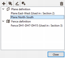
Section definition: Click ... in the Panel / Fence definition area to access the Section definition window. From this panel you can import, copy, rename, export or delete sections.

-
Click Import section to pop up the Import section task and import a section definition contained in an xml file.
-
 Click Duplicate to copy the selected section.
-
 Click Rename and enter the new name for the selected section.
-
 Click Export section to pop up the Export section task and export the selected section in an xml file.
-
 Click Delete to definitely remove the selected section(s) from the project.
-