Layer Tools
Selection Tools
The following tools allow you to make selections on a given layer. Remember that you need to select a layer in the layer list before starting an action.
-
Click Sample Selection to display the list and select one element:
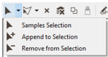
- Select Samples Selection and click on one sample or one zone to select it. If you want to select several samples hold down mouse’s left button and draw a rectangle including the target samples. Note that each time you add one or several samples to the selection, the previously selected samples are removed from the selection.
- Select Append to Selection to add samples to the current selection. Click the samples/zones to add them to the selection or hold down the mouse’s left button and draw a rectangle to catch the target samples.
- Select Remove from Selection to remove samples/zones from the current selection.
-
Click Polygon Selection to display the list and select one option:
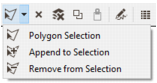
- Select Polygon Selection to select samples with a polygon. Just click on the map view to draw polygons as you want and select the zones/samples. This selection will erase the previous one.
- Select Append to Selection to add samples to the current selection with a polygon. Just click on the map view to draw polygons as you want and select the zones/samples.
- Select Remove from Selection to remove zones/samples from the current selection by drawing a polygon in the map view.
-
 Select Clear Layer Selection to clear the selection on the current layer.
-
 Select Clear Selection on all Layers to clear the selection on all the layers.
-
 Click Copy Selected Points / Polygon(s) to Clipboard to copy selected points / polygon(s) from the current layer to the clipboard. This functionality has to be combined with the
  Paste From Clipboard tool to paste point(s) / polygon(s) previously copied.


Layer Edition
The following tools require the selection of a layer to activate them:
Create new
-
 Select a Point layer and click Start Editing to enable the following edition tools associated to the point data.
 -
 Click Create Point and add as many samples as you want by clicking the correct locations in the map view.
-
 Click Delete Point and select a sample in the map view to delete it.
-
 Click Remove Point and select a sample in the map view to change its location.
Click a second time Stop Editing to leave this mode and disable the edition tools.
-
-
 Select the
 -
 Click Select Polygon To Edit and select a polygon. You will be able to edit this polygon.
-
 Click Create Polygon and digitalize a polygon. Once you have digitalized your polygon right click the map view to end the polygon creation.
-
 Click Delete Polygon and click the polygon that you want to delete.
-
 Select a polygon, click Add Contour and digitalize a new contour which will be added to the polygon.
-
 Select a polygon, click Add Hole and digitalize a hole inside the polygon.
-
Select a polygon, click Add Vertices and click on the edge of the current polygonto add a node.
-
Select a polygon, click Delete Vertices and click a node of the polygonto delete it.
-
Select a polygon, click Move Vertices and click a node of the polygon to move it.
-
 Click Undo last modification to undo the last modification.
-
 Click Redo last modification to redo the last modification.
When digitizing polygons, the snapping functionality (magnetism) is available by default. When you move your cursor close to an existing point (less than 10 pixels), this one is automatically snapped. The cursor is modified and a point appears. This ensures that the new point will have exactly the same coordinates as the snapped point. In this way, adjacent polygons are really adjacent, with neither superposition nor holes between them.
By pressing the Ctrl keyboard, the snapping is deactivated.
A “snap to direction” mode, to display vertical, horizontal or 45° lines, is also available by pressing Shift+Ctrl.
-
-
 Select a Polyline layer and click Start Editing to enable the following edition tools associated to the polylines:
-
 Click Select Polyline To Edit and select a polyline. You will be able to edit this polygon.
-
 Click Create Polyline and digitalize a polyline. Once you have digitalized your polygon right click the map view to end the polygon creation.
-
 Click Delete Polyline and click the polyline that you want to delete.
-
Select a polyline, click Add Vertices and click on the edge of the current polyline to add a node.
- Select a polyline, click Delete Vertices and click a node of the polyline to delete it.
-
Select a polyline, click Move Vertices and click a node of the polyline to move it.
-
Click Undo last modification to undo the last modification.
-
Click Redo last modification to redo the last modification.
A polyline can be closed or not. Blue points are used to indicate the beginning and the end of a polyline.
When digitizing polylines, the snapping functionality (magnetism) is available by default. When you move your cursor close to an existing point (less than 10 pixels), this one is automatically snapped. The cursor is modified and a point appears. This ensures that the new point will have exactly the same coordinates as the snapped point. In this way, adjacent polylines are really adjacent.
By pressing the Ctrl keyboard, the snapping is deactivated.
A “snap to direction” mode, to display vertical, horizontal or 45° lines, is also available by pressing Shift+Ctrl.
-
-
If the current layer is a geographic raster file (a raster image), click
 Start Transformation to enable the following tools:
-
 Select Move Image and click on the image moving and holding down the left mouse button to translate the image. During the translation, the image is transparent, this to facilitate positioning of a known point of the image onto its real location on the background map.
-
 Select Resize Image and click on the image moving your mouse to increase or decrease the image. Two black circles materialize the scale difference. The transformation center is represented as a yellow ring.
-
 Select Rotate and Resize Image and click on the image moving and holding down the left mouse button to rotate and/or increase/decrease the image. Two black circles materialize the scale difference as two black lines materialize the orientation difference. The transformation center is represented as a yellow ring. This tool facilitates positioning of a known point of the image onto its real location on the background map keeping fixed the point at the transformation center.
-
 Select Move the Transformation Center and click at the fixed point location that will be used as transformation center during scaling and/or rotation.
-
Click Undo last modification to undo the last modification.
-
Click Redo last modification to redo the last modification.
Note: It is impossible to undo the modification when the transformation has been applied, i.e. when you have clicked on Accept Transformation.
-
-
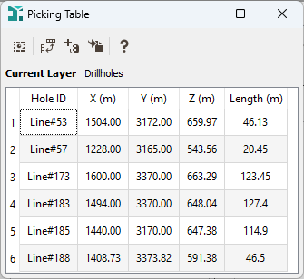
If the current layer is a points layer, a boreholes tops layer or a grid layer, interactively select the objects of your choice thanks to the selection tools
 or
or  and click
  Display Data Information to see the different variables associated to the selected objects. For more information about this functionality, please see Picking Table.
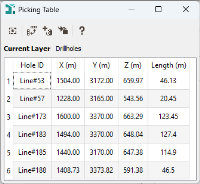
-
 If the current layer is a boreholes layer, select boreholes tops thanks to the Selection tools and click Display Logs to display the values of a variable along the boreholes in a dedicated Display Logs window.