
Configure Stope Face Polygons
Stope Face Polygonsis one type of Advanced Slice Frameworks.
The polygons are custom closed string shapes representing the front face of each stope. MSO extrudes these shapes into tubes based on additional parameters.
Note: This is similar to the process used to Configure Stope Trapezoids but a simpler 4-point rectangle defines a profile shape for extrusion instead of a 6 point trapezoid.
This method defines the stope shape in long section, and the projection of this shape in the W-axis direction (the transverse direction) forms the face of the stope shape "tube".
Specification of the stope shape dimensions can be individually specified within the extents of the framework. This may be of particular use for orebodies that require irregularly located or shaped pillars or require an irregular exclusion zone around say a shaft, workshop, and development access or require irregular stopes with say variable section end-walls so that they are at right-angles to the contour.
This framework type is often used when stope outlines are manually designed in plan or section.
Also see Configure Stope Trapezoids.
Activity steps
-
Display the Framework screen.
-
Expand Framework Type to select Advanced Framework, if not already selected.
-
Expand Advanced Type and select Stope Rectangles.
-
Add a new row to the table using + or insert one above the currently selected record using ←.
-
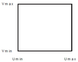
Enter the following values to define the polygon profile in the framework's coordinate space:
Description Usage & Effect Min U The lower (starting) coordinate in the U direction of the framework. Basically, the rectangle’s left boundary along strike or section spacing. Shrink or expand to shift or limit the stope’s start point along strike. Max U The upper (ending) coordinate in the U direction (the rectangle’s right boundary). Together with Min U, this sets the horizontal span of the stope rectangle in the framework’s strike direction. Min V The lower (starting) coordinate in the V direction of the framework. It is the rectangle’s bottom boundary (level or dip position). Controls how far down the rectangle extends in height/dip direction. Max V The upper (ending) coordinate in the V direction — the rectangle’s top boundary. Together with Min V, this defines the vertical height of the rectangle. Position A label or ID for the rectangle’s location in the framework (often a section or level index or tube ID). Used for identifying and organizing rectangles, especially if you have multiple custom faces in the framework. -
Save your settings.
Related topics and activities