
Configure Stope Trapezoids
Stope Trapezoidsis one type of Advanced Slice Frameworks.
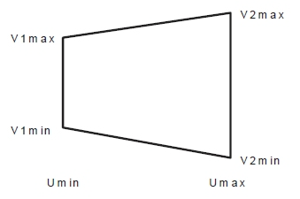
This option allows you to determine the additional point settings required to define the non-orthogonal shape. A trapezoid stope-shape has two opposite parallel sides and is defined by the coordinates (umin, umax, v1min, v1max, v2min, v2max).
Note: This is similar to the process used to Configure Stope Face Polygons but a more complex 6-point shape defines a profile shape for extrusion instead of a simpler 4-point rectangle.
This method defines the stope shape in long section, and the projection of this shape in the W-axis direction (transverse direction) forms the face of the stope shape "tube".
Specification of the stope shape dimensions can be individually specified within the extents of the framework. This may be of particular use for orebodies that require irregularly located or shaped pillars or require an irregular exclusion zone around say a shaft, workshop, and development access or require irregular stopes with say variable section end-walls so that they are at right-angles to the contour.
This framework type is often used when stope outlines are manually designed in plan or section.
Activity steps
-
Display the Framework screen.
-
Expand Framework Type to select Advanced Framework, if not already selected.
-
Expand Advanced Type and select Stope Trapezoids.
-
Add a new row to the table using + or insert one above the currently selected record using ←.
-
Enter the following values to define the polygon profile:
Description Usage & Effect Min U The lower (starting) coordinate in the U direction of the framework. Basically, the position of a bounding regular rectangle’s left boundary along strike or section spacing (with the trapezoid fully enclosed). Shrink or expand to shift or limit the stope’s start point along strike. Max U The upper (ending) coordinate in the U direction (the bounding rectangle’s right boundary). Together with Min U, this sets the horizontal span of the stope rectangle in the framework’s strike direction. Min V1 The lower (starting) coordinate of the trapezoid in the V direction of the framework. It is the trapezoid’s bottom left boundary (level or dip position). Controls how far down the trapezoid's left side extends in height/dip direction. Max V1 The upper (ending) coordinate in the V direction — the trapezoid’s top left boundary. Together with Min V1, this defines the vertical height of the left of the trapezoid. Min V2 The trapezoid's lower right coordinate. Controls how far down the trapezoid's right side extends in height/dip direction. Max V2 The trapezoid's upper right coordinate Together with Min V2, this defines the vertical height of the right of the trapezoid. Position A label or ID for the rectangle’s location in the framework (often a section or level index or tube ID). Used for identifying and organizing rectangles, especially if you have multiple custom faces in the framework. -
Save your settings.
Related topics and activities