Create Surface Roads
To access this screen:
-
Run the command create-surface-roads.
-
Use the quick key combination 'csr'
Create roads on a reference topography, using a centreline and various parameters describing road profile and cut and fill batters.
The general workflow for creating a surface road is:
- Define initial road settings: select a loaded topography wireframe and
- Copy or create a road reference line; you can either digitize a new line or use any loaded string object. Lines can represent the center line, left edge or right edge.
- Edit road properties, such as vertical and horizontal gradient adjustments.
- Generate road information, such as cross-sections, outlines or wireframe surface. These settings will determine the profile of your road as it traverses the topography, including deviations from the topography elevation values.
- Generate the benches and angles needed to support the road in the topography. These batter surfaces and volumes are used to calculate independent cut and fill volumes.
- Update the topography to include the new road and batters.
- Save surface road data to the database.
Where information is missing from previous steps, subsequent controls are disabled and information posted alongside indicating missing information.
Subsequent edits to earlier steps, such as editing the centerline after road batters have been generated, removes existing data for later steps. Loaded data objects remain, but may be emptied if they no longer contain valid information.
Steps may also be run automatically on completion of the previous step, be checking Auto apply.

Tip: run each step manually and individually first, to determine processing times and results. Subsequent runs can then be automatic.
Saving Surface Road Data
Clicking Save transfers all generated surface road data to your selected location and leave the Create Surface Roads task open, alternatively you can Save & Close or simply Close if you don't wish to save your changes.
To set up initial parameters for surface road generation:
- Any loaded wireframe can be used as the topography by selecting it in the Topography list. It is assumed this is a valid DTM (no additional validation is performed). The default selection is the current wireframe object.
- Define a Road Name. Each unique road name is associated with a range of data objects that represent the aspects of the surface road, including all outline, surface and solids data.
- Decide on a Road Width.
-
Review the initial Cut and Fill Volumes.
These values provide an initial check on the volume of material to be moved or extracted. You can see both Cut, Fill and Excess volumes.
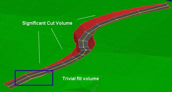
For example, the road excavation below (showing an updated topography from later in the process) results in predominantly cut operations, will a small fill to shore up the lower left road end:
In this case, the Cut volume is significantly higher than the Fill volume, leaving a sizeable Excess volume.
- Digitize or select a reference line - this is explained in more detail in the section below.
Note: if you have already created a road and enter a new Road Name, you are asked if you want to copy the settings from the previous road. This is a good option if you're experimenting with road layout variations. If previous road data is unsaved, you'll get the chance to save it before copying.
The Surface Roads Toolbar

Along the top of the panel there is a command toolbar containing access to road generation and topography update commands.
See Create Surface Roads Toolbar.
Reference Line Adjustment

Road centerline data can be adjusted either using a horizontal or vertical adjustment of string vertices. The type of editing is determined by expanding either the Reference Line Horizontal Adjustment or Reference Line Vertical Adjustment command groups.
See Surface Road Reference Line Adjustment.
Gradient Reporting
Road gradient constraints let you ensure your generated road geometry is practical for your fleet.
See Surface Road Gradient Reporting.
Cut & Fill Volumes
Cut and fill volumes are calculated throughout road generation.
See Surface Road Cut and Fill Volumes.
Road Sections and Parameters
The Road Parameters group and associated Generate Road button are used to calculate the road surface from the reference line. This will either be a simple fixed-width road along the full length of the reference line, using the same cross-sectional shape at each point, or a more complex arrangement where road reference line shapes can potentially vary at any point along the line.
See Surface Road Sections and Parameters.
Designing Road Batters
Batters connect the road surface to the surrounding topography. Fill batters will usually have different structural requirements to cut batters, so there are two different but functionally identical control groups for defining them. Benches may come in two forms: parallel and horizontal.
See Surface Road Batter Design.
Update the Topography
Once the road and batters look as desired, the Update Topo button can be used to create a copy of the original topography.


