Surface Road Bench Design
The Create Surface Roads screen is used to create roads on a reference topography, using a reference line and various parameters describing road profile and cut and fill batters.
After running the command, the Create Surface Roads dialog is displayed in a dockable control bar.
Note: you can only generate batters if a topography is selected and a road has been generated.
Benches (sometimes referred to as "batters") connect the road surface to the surrounding topography and either represent fill volumes (material introduced to support the road above or cut volumes representing excavations to create a surface road that meets operational constraints such as gradient and width.
Fill benches will usually have different structural requirements to cut benches, so there are two different but functionally identical control groups for defining them.
The Face angle is the angle of the bench faces, and is always specified in degrees.
Benches may also have benches at fixed elevation intervals, in order to comply with geostructural or access requirements. Benches can enabled by selecting either or both of the Benches every check boxes and updating the bench height in the adjacent edit box.
For example, to introduce a 1 meter bench for every 10 meters of 60 degree fill batter; using the Fill control group, specify "60" degrees for the Face angle. enable the Benches every check box and enter "10" for the bench height:
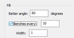
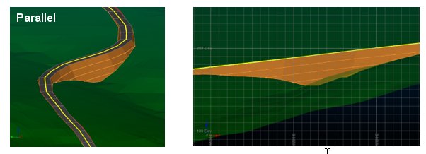
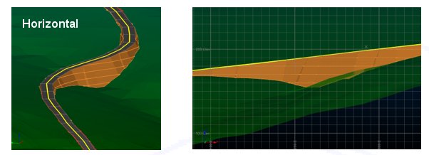
Benches come in two forms: parallel and horizontal.
- Parallel benches follow the elevation changes in the road, so the vertical distance from the road surface to the bench is the same at any point along the road.
-
Horizontal benches: in addition to bench height, horizontal benches may also have a separate Horizontal - offset defined. Bench elevations will notionally start at the offset and then repeat according to the bench height. For example; benches required at elevations of 25, 35, 45 etc., may have a bench height of 10 and an offset of 5. Note that the offset does not need to lie within the range of elevations being used by the road. In the images below, the top image shows an Elevation offset of 1 whilst in the bottom image the value has been increased to 2:
1 metre elevation offset:
2 metre elevation offset:
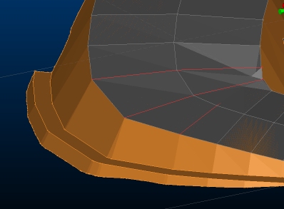
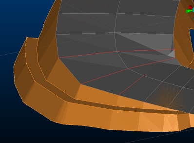
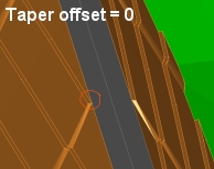
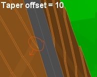
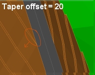
You can also change the way a batter tapers at the end of the horizontal berms using the Taper distance setting. For example, in the images below, a Taper offset of zero results in an obvious step shape where the berm meets the road (and in each lower berm). The second image represents the same data with a Taper offset of 10, and the final image shows a Taper offset of 20:
Once you've set up your bench properties, click Generate Batters to create the selected output object(s).
Zero width benches
Although bench widths would normally be non-zero, zero-width benches are also allowed. Batters are generated according to the slope angle to calculate outline strings for each bench. These strings are then linked together to create the batter wireframes.
Tip: when no bench height is defined, the calculation uses an internal bench height which is guaranteed to intercept the wireframe. If there is a considerable elevation change in the wireframe, or the road has a lot of curves compared to the internal bench height, then it is possible that some detail may get lost in the final bench outline, affecting the batter surfaces. In the event that the calculated batters do not look correct when not using benches, it is recommended that the generation is repeated with a nominal bench height and 0 bench width as that will allow the intermediate detail to be preserved.
Cut & Fill Volumes
On generation of the batters, the system will automatically calculate the associated cut and fill volumes and report them at the top of the dialog. If it was not possible to get valid volume for either cut or fill, this is shown as “<invalid>”. In this situation the generated batter solids can be used to identify the problem – often that the road was too close to the edge of the topography.
See Cut & Fill Volumes for Surface Roads.
Output Options
Each of the batters can be output as a distinct data object:
-
Output bench strings
Naming convention: [Road Name]_CutBatterStrings/FillBatterStrings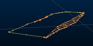
An outline around the batter surface, and toe/crest strings for the benches. Cut and fill batter string objects are created separately.
-
Output bench surfaces
Naming convention: [Road Name]_ CutBatterSurface/FillBatterSurface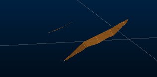
A wireframe of the batter and bench faces. Cut and fill batter surfaces are output as separate wireframe objects.
-
Output bench solids
Naming convention: [Road Name]_ CutBatterSolid/FillBatterSolid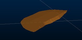
A wireframe enclosing the volume between the road, batter and the topography. Cut and fill batter solids are output as separate wireframe objects.
-
Output combined bench and road outline strings
Naming convention: [Road Name]_CombinedBatterOutline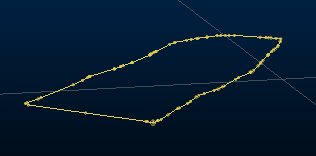
A combined outline string may be generated around both the batter surfaces and road surface, marking their intersection with the topography.
Related topics and activities

