|
|
Using generate-controls-from-holes-intercepts |

Contours from Drillhole Intercepts - Input Data
To access this dialog:
-
Load a drillholes file, then activate the Report ribbon and select Contours | Generate Contours | Generate Contours from Drillhole Intercepts
-
Run the command 'generate-contours-from-holes-intercepts' using the command line.
|
|
Contouring commands are scriptable. You can find out more using this Knowledge Base Article. |
Generate contour strings from an input desurveyed drillholes data object.
This method of contouring involves interpolation of a surface map between drillhole intercept positions. This function makes use of the generate-contours-from-holes-intercepts command.
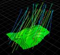
Contouring Drillhole Data
The input to this function is a loaded drillhole object. The following optional inputs are also supported:
- Strings to indicate fault lines and/or clipping regions
- Additional point data in the form of actual points or string vertices
The command optionally generates an output string file containing contours at nominated elevations, a grid model and/or a wireframe surface object.
It is not possible to generate a distance-from-samples style contour map with this command.
This tool supports the following:
- Choice of different interpolation algorithms
- Choice of highest or lowest elevation maps
- Anisotropy
- Data smoothing
- Region clipping
- Faulted data
- Smooth contour lines
- Gridded data output
- Surfacing
For more general information on this command, please refer to:
Click Next on this screen to validate the values (warnings will be issued if insufficient data has been provided to continue). Once validated, you will be shown the Gridding panel.
|
|
Use the Back and Next buttons to access functionality in the Generate Contours wizard. Once you have completed setting you your parameters, click Finish to create your output object(s). Once data has been generated, your previous settings can be retrieved in a subsequent session using Restore. |
Field Details:
Drillhole Data:
Input drillhole data is mandatory for this command.
Object: only enabled if at least one drillhole (static) data object is loaded. Use this to select a desurveyed drillhole object containing the attribute and key field value to be modelled.
Selected drillholes: select this option if you wish to contour a subset of the specified Object, you will need to pre-select/highlight drillhole data first, then click Store Current Selection.
This creates a subset object in memory, which is committed to the contouring process when you click Next. If no drillhole data is selected, all samples will be considered during modelling, otherwise, the subset data will be used instead. The subset object is transient; for example, clicking the Object radio button at this point will delete the temporary subset data, requiring you to click Store Current Selection again if you wish to reinstate the previous context.
|
|
If you have selected an attribute to model, it is important that at least one sample in the selection pool contains non-absent information for that attribute. If no non-absent data values can be found, an alert will be displayed. |
If a selection has been made, the number of entities selected will appear as a read-only field to the right of the Store Current Selection button.
Contour attribute: select the attribute in the input Object that contains the key field value you wish to model. This can be any alphanumeric attribute.
If you select an attribute that contains more than 100 unique values, you will be asked to confirm your action.
Value: all unique values of the Contour attribute are listed here. Select the value to be modelled.
Highest/Lowest elevation: choose whether you want to model the drillhole intercept (for the specified key field) at the highest or lowest location. If multiple intervals exist on a sample, the highest/lowest of all intervals will be used.
Point Data:
When generating a surface through drillhole intercepts you can include
additional points which haven't come from the drillholes. These may
be survey pegs, existing contours or dummy points you want to use
to influence the results. If strings are specified, the corresponding
vertices will be treated as points.
None: this is the default selection; no additional points will be considered in contouring.
Object: if a strings or points object is loaded, this option is available. Select an existing object from which to derive extra points. Only one object can be selected.
Selected points:
to add any loaded string or point data to the contouring calculation
(even a mixture), select the data you want in any 3D window, the click
Store Current Selection. You
will see the number of items added to the collection on the right
(a string counts as a single item, but all vertices will be used).
Faults:
For more information on fault modelling with this command, click
here.
None: this is the default selection; no faulting will be applied.
Object: if a strings object is loaded, this option is available. Select an existing string object to create discontinuities in your output contour data. As with drillholes and clipping polygons (see below), you can pre-select strings for inclusion in a faults subset object; enable Selected strings, select the string(s) to use, then click Store Current Selection. This object is then committed to contouring when you click Next.
Selected Strings: to add other loaded strings to as discontinuity data, select them in any 3D window and click Store Current Selection. You will see the number of items added to the collection on the right.
Clipping Polygons:
Clipping Polygons are closed
strings. Data will not be generated inside
of the closed polygon(s). You can use a loaded strings object (either
in full or a selected subset of strings). A general procedure demonstrating
clipping polygon usage can be found here
(the example uses points, but the principle is identical for drillhole
output).
None: this is the default selection; no clipping will be applied.
Object: if a strings object is loaded, this option is available. As with faults and clipping polygons (see below), you can pre-select strings for inclusion in a subset object; enable Selected strings, select the string(s) to use, then click Store Current Selection. This object is then committed to contouring when you click Next.
Selected Strings: to add other loaded strings to as boundary data, select them in any 3D window and click Store Current Selection. You will see the number of items added to the collection on the right.
When using clipping polygons, you can choose whether you want to retain the data inside or outside the closed boundary for contour object output. Select Inside or Outside.
Plane Orientation (not available for generate-distance-contours command):
By default, contours are constructed using a flat, unrotated plane. You can change the orientation of the plane used for contouring here, however, if you set your plane to be rotated (that is, by setting azimuth or dip to a non-zero value) you won't be able to set up custom grid object settings on the Data Output panel.
Horizontal/North-South/East-West: pick either of these for a predefined, orthogonal orientation.
Current Section: use the currently active section for contouring.
Current View: ignore any loaded planes and simply use the line of sight for contouring calculations.
Copyright © Datamine Corporate Limited
JMN 20045_00_EN