|
|

Contours from Points - Input Data
To access this dialog:
-
Load a points or string file, then activate the Home ribbon and select Create | Contours.
-
Run the command 'generate-contours-from-points' using the command line.
The contents of this dialog will depend on the command that you have run to access it:
- generate-contours-from-points: all fields described here can be accessed
- generate-distance-contours: a subset of the described fields can be accessed. See "Field Details" for more information
Your product contains functionality to generate contour strings from an input points data object.
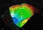
Contouring is the process of tracing contours - lines of equal z-value (such as grade, elevation, seismic travel time or drillhole intercept positions) - on a grid for representation of the surface on a map.
|
|
Contouring commands are scriptable. You can find out more using this Knowledge Base Article. |
|
|
Use Back and Next to access functionality in the Generate Contours wizard. Once you have completed setting you your parameters, click Finish to create your output object(s). Once data has been generated, your previous settings can be retrieved in a subsequent session using Restore. |
Contouring Point/String Data
The input to this function is a loaded points or string object. The command optionally generates an output string file containing contours at nominated elevations, a grid and/or a wireframe surface object.
- generate-contours-from-points offers:
- Choice of different interpolation algorithms
- Anisotropy
- Data smoothing
- Region clipping
- Faulted data
- Smooth contour lines
- Gridded data output
- Surfacing
- generate-distance-contours offers:
- Smooth contour lines
- Gridded data output
- Distance-from-sample maps
For more general information on these commands, please refer to:
- Contours from Points
- Contours from Points - Procedures
- generate-contours-from-points
- generate-distance-contours
Your
contouring object data is then committed to contouring when you click
Next on this screen. This
data set is retained no matter what happens to the input data objects;
modifying them or unloading the base objects will have no effect on
the contouring process. If you wish to include object adjustments
made since the dialog was opened, it is necessary to close and reopen
the dialog and re-select the data objects (point, faults and/or clipping
polygons).
Field Details:
Point Data:
Input points data is mandatory for this command. This can either be stored in a points object, or the vertices of a string object can be used instead.
Object: only enabled if at least one point or string data object is loaded. Use this to select a points or string object containing the attribute and key field value to be modelled.
Selected points: select this option if you wish to contour a subset of the specified Object, you will need to pre-select/highlight data first, then click Store Current Selection.
This creates a subset object in memory, which is committed to the contouring process when you click Next. If no drillhole data is selected, all points will be considered during modelling, otherwise, the subset data will be used instead. The subset object is transient; for example, clicking the Object radio button at this point will delete the temporary subset data, requiring you to click Store Current Selection again if you wish to reinstate the previous context.
If a selection has been made, the number of entities selected will appear as a read-only field to the right of the Store Current Selection button.
|
|
If you have selected an attribute to model, say, for grade contouring, it is important that at least one point in the selection pool contains non-absent information for that attribute. If no non-absent data values can be found, an alert will be displayed. |
Contour attribute (not available for generate-distance-contours command): select the attribute in the input Object that contains the key field value you wish to model. This can be any numeric attribute, and if the column "_Z_Coord" exists, it will be selected by default.
If you wish to create a distance-from-samples contour map, run the generate-distance-contours command which shows a streamlined version of the Generate Contours dialog.
If you select an attribute that contains more than 100 unique values, you will be asked to confirm your action.
Faults (not available for generate-distance-contours command):
For more information on fault modelling with this command, click
here.
None: this is the default selection; no faulting will be applied.
Object: if a strings object is loaded, this option is available. Select an existing string object to create discontinuities in your output contour data. As with point data and clipping polygons (see below), you can pre-select strings for inclusion in a faults subset object; enable Selected strings, select the string(s) to use, then click Store Current Selection. This object is then committed to contouring when you click Next.
Clipping Polygons (not available for generate-distance-contours command):
Clipping Polygons are closed strings. Data will not be generated
inside of the closed polygon(s).
You can use a loaded strings object (either in full or a selected
subset of strings). A general procedure demonstrating clipping polygon
usage can be found here
(the example uses points, but the principle is identical for drillhole
output).
None: this is the default selection; no clipping will be applied.
Object: if a strings object is loaded, this option is available. As with faults and clipping polygons (see below), you can pre-select strings for inclusion in a subset object; enable Selected strings, select the string(s) to use, then click Store Current Selection.
When using clipping polygons, you can choose whether you want to retain the data inside or outside the closed boundary for contour object output. Select Inside or Outside.
Plane Orientation (not available for generate-distance-contours command):
By default, contours are constructed using a flat, unrotated plane. You can change the orientation of the plane used for contouring here, however, if you set your plane to be rotated (that is, by setting azimuth or dip to a non-zero value) you won't be able to set up custom grid object settings on the Data Output panel.
Horizontal/North-South/East-West: pick either of these for a predefined, orthogonal orientation.
Current Section: use the currently active section for contouring.
Current View: ignore any loaded planes and simply use the line of sight for contouring calculations.
Copyright © Datamine Corporate Limited
JMN 20045_00_EN